(4) Remove the fog lamp switch fr om t he face of
the cluster bezel.
INSTALLATION
WARNING: To avoid personal injury or death, on
vehicles equipped with airbags, disable the supple-
mental restraint system before attempting any
steering wheel, steering column, airbag, seat belt
tensioner, or instrument panel component diagno-
sis or service. Disconnect and isolate the battery
negative (ground) cable, then wait two minutes for
the system capacitor to discharge before perform-
ing further diagnosis or service. This is the only
sure way to disable the supplemental restraint sys-
tem. Failure to take the proper precautions could
result in accidental airbag deployment.
(1) Position the fog lamp switch to the pr oper
mounting hole on the face of t he cluster bezel (Fig.
16).
(2) Usin g hand pressure, push the fog lamp switch
firmly and evenly in to th e swit ch moun ting hole of
the cluster bezel unt il both of the la tches on the
switch body are fully en gaged.
(3) Reinstall the cluster bezel onto the instrumen t
pa nel. (Refer to 23 - BODY/INSTRUMENT PANEL/
CLUSTE R BEZEL - INSTALLATION).
(4) Reconnect t he battery negative cable.
FRON T LAM P U N I T
REMOVAL
(1) Disconn ect and isolate the battery nega tive
cable.
(2) Remove th e fron t gr ille fr om th e vehicle. (Refer
to 23 - BODY/EXTERIOR/GRILLE - RE MOVAL).
(3) Remove th e two screws th at secure the cover at
the inboa rd side of t he front lam p u nit (Fig. 18).
(4) Remove the cover from t he fron t lamp u nit.
(5) From t he engine compart ment , disconnect th e
vehicle wire harness connect or fr om t he connector
recepta cle for th e front lamp unit.
(6) Remove th e four screws tha t secur e the front
lam p u nit to the fr ont of th e veh icle.
(7) Remove t he front lamp un it fr om th e fr ont of
the vehicle.
INSTALLATION
(1) Position the front la mp unit to the fron t of th e
vehicle (Fig. 18).
(2) In st all and tight en the fou r screws tha t secu re
the fr ont lamp unit to the fron t of the vehicle.
(3) From the engine compa rtment, r econnect the
vehicle wire har ness connector t o the conn ector
recepta cle for th e front lamp unit.
(4) Position the cover to the fr ont lamp unit.
(5) In st all and t igh ten the two screws that secure
the cover at the in board side of th e front lamp u nit.
(6) Reinstall t he front grille onto th e vehicle.
(Refer t o 23 - BODY/EXTERIOR/GRILLE - INSTAL-
LATION).
(7) Reconnect t he battery negative cable.
(8) Check a nd adjust the fr ont lamp alignmen t a s
required. (Refer to 8 - ELE CTRICAL/LAMP S/LIGHT-
ING - EXTERIOR/FRONT LAMP UNIT - ADJ UST-
MENTS).
Fig. 17 Fog Lamp Switch Remove/Install
1 - FOG LAMP SWITCH
2 - LATCH (2)
3 - CLUSTER BEZEL
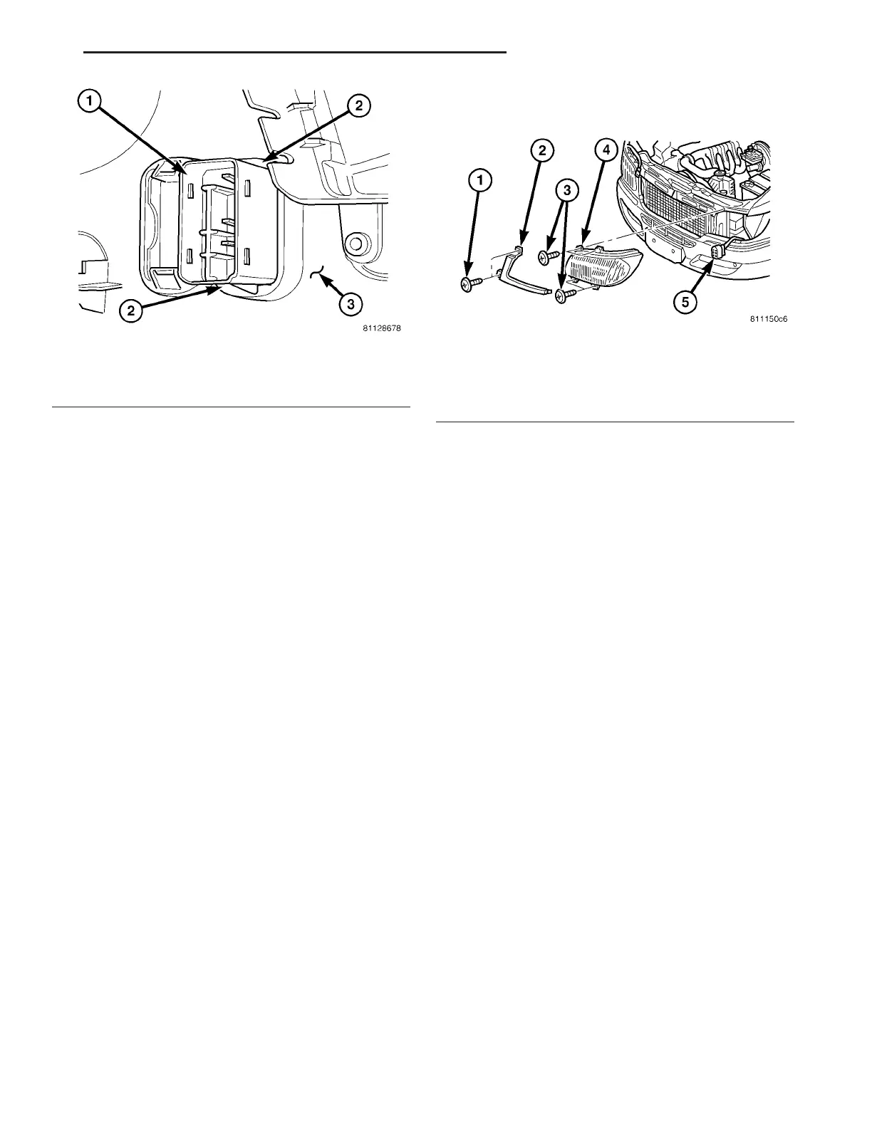
Fig. 18 Front Lamp Unit Remove/Install
1 - SCREW (2)
2 - COVER
3 - SCREW (4)
4 - LAMP UNIT
5 - WIRE HARNESS CONNECTOR
VA LAMPS/LIGHTING - EXTERIOR 8L - 13