(4) Use th e m easurment and table below t o group
cylinder bores:
Standard size 88.0 mm
Group code letter A 88.000-88.006 mm
Group code letter X 88.006-88.012 mm
Group code letter B 88.012-88.018 mm
Wear limit in longitudinal
in transverse direction
0.020 mm
Permissible variation of
cylinder shape (when
new)
0.000-0.014 mm
CRAN K SH AFT
DESCRIPTION
The en gine featu res a forged cran ksha ft supported
by six bea rin gs. The bearing caps are machined
toget her with the cranksha ft a nd must not be in ter-
changed. Th e bearing surfaces are induct ion har d-
ened. The connect ing rods and m ain bearing jour nals
are fillet ed. An opt ional vibr ation da mper with a sec-
ond pu lley is u sed to drive an addit ional A/C com-
pr essor.
STANDARD PROCEDURE - MEASURE CRANK-
SHAFT AND BLOCK JOURNALS
NOTE: After any bearing damage occurred, remove
all debris which is present in the main oil gallery,
connecting rod bores, and in the crankshaft and oil
galleries. Include removal of the inserting steel ball
of the main oil gallery before cleaning.
(1) Remove cra nksh aft (Refer to 9 - E NGINE/EN-
GINE BLOCK/CRANKSHAFT - REMOVAL).
(2) Clean all engine pa rts th oroughly.
CAUTION: After bearing has damage has occurred,
replace connecting rods which have suffered over-
heating because of bearing damage. The connect-
ing rod must not have any cross scores and
notches.
(3) In spect connecting r od. If damage is pr esent,
inspect cra nksh aft, r eplace as necessa ry.
(4) In spect cr ankcase.
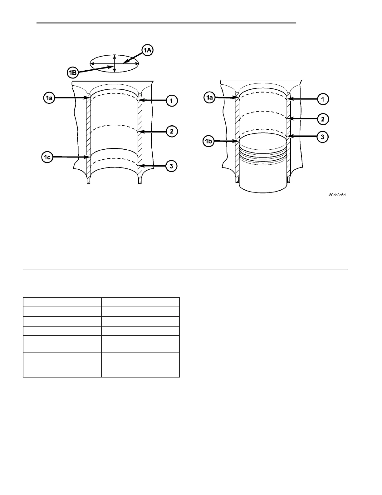
Fig. 31 MEASURING CYLINDER BORES
1 - MEASURING POINT OF CYLINDER BORE
2 - MEASURING POINT OF CYLINDER BORE
3 - MEASURING POINT OF CYLINDER BORE
1a - UPPER REVERSAL POINT OF #1 PISTON RING
1b - BOTTOM DEAD CENTER OF PISTON
1c - BOTTOM REVERSAL POINT OF OIL SCRAPER RING
1A - LONGITUDINAL DIRECTION
1B - TRANSVERSE PDIRECTION
VA ENGINE 9 - 39