and pull th at edge of the la mp a way fr om its mou nt-
ing location (Fig. 1).
(3) Pull the dome lamp/intr usion sensor unit from
its mountin g location far en ough to access an d dis-
connect the veh icle wir e harness from th e la mp con-
nector r eceptacle.
(4) Remove the dome lamp/intr usion sen sor u nit
from its mounting locat ion.
INSTALLATION
(1) Position t he dome lamp/intrusion sensor u nit to
its mounting locat ion.
(2) Reconnect t he vehicle wire harn ess conn ector
to the dom e lamp/intr usion sensor un it connector
recepta cle.
(3) Position the edge of the dom e lam p/intrusion
sensor unit housin g opposite fr om the retainer clip
into the mounting hole.
(4) Push fir mly and evenly on th e notch ed edge of
the dome lamp/intr usion sensor unit housin g until
the r etainer clip la tches into place.
(5) Connect the batt ery n egat ive cable.
SECU RI T Y SY ST EM M ODU LE
REMOVAL
(1) Disconn ect and isolate the battery nega tive
cable.
(2) Remove driver seat cu sh ion.
(3) Remove mountin g fasten ers.
(4) Disconn ect wire har ness connect or.
INSTALLATION
(1) Connect wire har ness connector.
(2) Position module. Install and tight en moun ting
fasten ers.
(3) In st all driver seat cushion.
(4) Connect batt ery n egat ive cable.
SEN T RY K EY REM OT E EN T RY
MODULE
DESCRIPTION
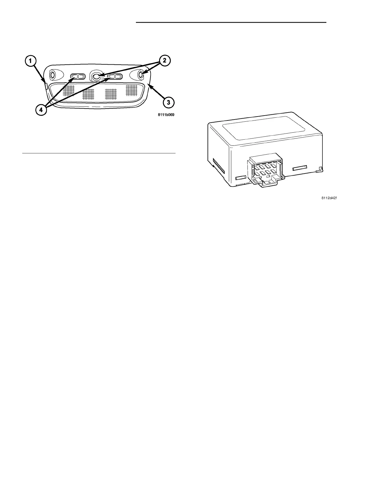
The Sen try Key Remot e En try Module (SKREEM)
(Fig. 2) performs the fun ction s of t he Sent ry Key
Im mobilizer Modu le (SKIM) and the Remote Keyless
Entry (RKE ) module.
SENTRY KEY IMMOBILIZER
The Sentr y Key Immobilizer System (SKIS)
authenticates an electronically coded Transponder
Key pla ced into the ignition a nd sen ds a va lid/in valid
key messa ge to the Engine Con trol Module (ECM)
based upon the result s. The “VALID/INVALID KE Y”
message communication is per formed using a r olling
code algorithm . A “VALID KE Y” message must be
sent to the E CM with in two seconds of ign ition ON
to free t he engine fr om immobiliza tion . This Con trol-
ler Area Net work (CAN) data bus message is sent to
the E CM after first going t hrough the SKREEM. The
SKREEM is located behind th e instrument cluster
and has a separ ately mounted ant enna ring moun ted
around th e ignition cylin der (Fig. 3) wh ich picks up
the t ransponder key sign al.
Fig. 1 DOME LAMP/INTRUSION SENSOR
1 - NOTCH
2 - SENSOR (3)
3 - HOUSING
4 - SWITCH (2)
Fig. 2 SENTRY KEY REMOTE ENTRY MODULE
(SKREEM)
8Q - 2 VEHICLE THEFT SECURITY VA