(5) In spect sta ndard size of cr ankshaft bearing
shells.
(6) In spect cr ankshaft bearing cap.
(7) Mount crankshaft radially.
(8) In spect cr ankshaft bearing play.
NOTE: Radial mounting of the main bearings of
standard size crankshaft is possible by assigning
the color-coded bearing shells.
ASSIGN CRANKSHAFT BEARING SHELLS
The oil pan rail of th e cylinder block is ma rked
with chisel punches indicating what bea ring shell are
used.
(9) Assign cra nksh aft bear ing shells.
(10) Mount crankshaft a xia lly.
(11) In spect cr ankshaft bearing play.
REMOVAL
(1) Remove en gin e (Refer to9-ENGINE-
REMOVAL).
(2) Remove t iming case cover (Refer to 9 -
ENGINE/VALVE TIMING/TIMING BELT / CHAIN
COVER(S) - REMOVAL)
(3) Remove en d cover. (Refer t o 9 - E NGINE/EN-
GINE BLOCK/CRANKSHAFT OIL SEAL - RE AR -
REMOVAL).
(4) Remove pist ons (Refer to 9 - ENGINE/ENGINE
BLOCK/PISTON & CONNECTING ROD -
REMOVAL).
CAUTION: The crankshaft bearing caps are num-
bered consecutively, beginning with the first crank-
shaft bearing cap at the front of the engine.
Attention must be paid to the way crankshaft bear-
ing caps fit.
(5) Unbolt cra nksh aft bear ing caps (Fig. 32).
(6) In spect crankshaft bearing caps and bolts for
wear and st retch ing.
(7) Remove crankshaft.
INSTALLATION
CAUTION: Oil the bearing shells before inserting
crankshaft.
CAUTION: Oil grooves in the thrust washers must
point toward the thrust collars of the crankshaft.
CAUTION: Thrust washers in the bearing cap each
have two retaining lugs as a anti-twist lock.
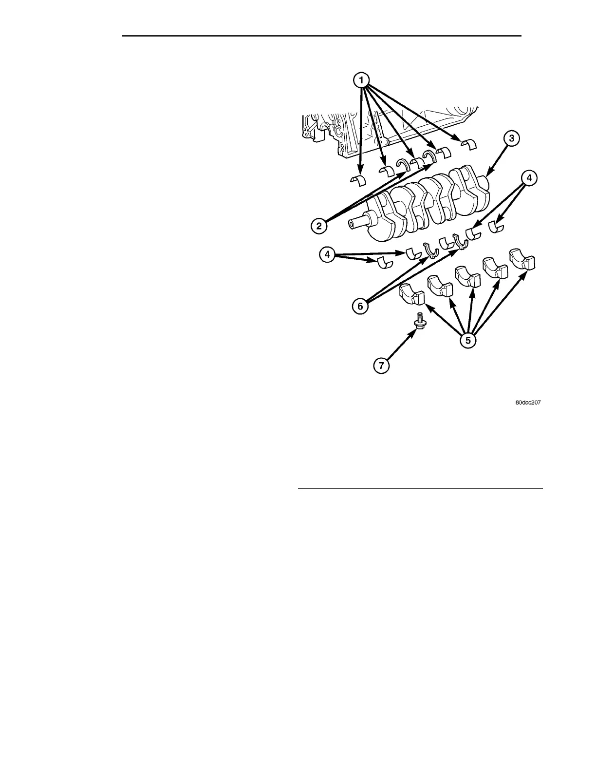
Fig. 32 CRANKSHAFT ASSEMBLY
1 - BEARING HALVES IN ENGINE BLOCK
2 - THRUST WASHERS IN ENGINE BLOCK
3 - CRANKSHAFT
4 - BEARING HALVES IN MAIN BEARING CAPS
5 - MAIN BEARING CAPS
6 - THRUST WASHERS IN MAIN BEARING CAPS
7 - MAIN BEARING BOLTS
9 - 40 ENGINE VA