REMOVAL
(1) Disconn ect nega tive battery cable.
(2) Remove va cuum line at vacuu m pump (Fig.
48).
NOTE: Observe position of driver on rear of pump.
(3) Remove va cuum pump a nd seals (Fig. 48)
(4) Clean all sealing surfa ces.
INSTALLATION
(1) Clean all sealing surfa ces.
(2) Position dr iver on rear of pump and insta ll vac-
uum pump with new seals. Tighten bolts to 14N·m
(124 lbs. in.). (Fig. 48)
(3) In st all vacuum line t o vacu um pump (F ig. 48).
(4) Connect nega tive bat tery cable.
WARNING: USE EXTREME CAUTION WHEN THE
ENGINE IS OPERATING. DO NOT STAND IN A
DIRECT LINE WITH THE FAN. DO NOT PUT YOUR
HANDS NEAR THE PULLEYS, BELTS OR FAN. DO
NOT WEAR LOOSE CLOTHES.
(5) St art th e engine and inspect for lea ks.
LEFT M OU N T
REMOVAL
(1) In st all engine su pport fixture #8534 with ada p-
tors #8534–16 and raise the engin e slightly.
(2) Raise and support the vehicle.
(3) Remove the engine m ount bolts (Fig. 49)
(4) Lower th e vehicle.
(5) Usin g th e engine support fixtu re # 8934, raise
the engine until the weight is no longer on th e
mounts.
(6) Raise and support the vehicle.
(7) Remove the engine m ount n uts an d r emove the
mount (Fig. 49)
INSTALLATION
(1) Position the engine mou nt into th e st op pla te
(Fig. 49)
(2) Position the en gin e mount into position an d
tighten t he retaining nuts to 45 N·m (33 lbs. ft.) (Fig.
49)
(3) Lower th e vehicle.
(4) Lower the engine on to the engine m ounts u ntil
they contact (Fig. 49)
(5) Hand tighten th e engine support to engine
mount bolt (Fig. 49).
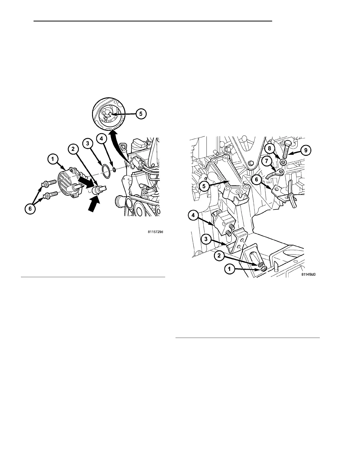
Fig. 48 VACUUM PUMP
1 - VACUUM PUMP
2 - VACUUM LINE
3 - O-RING
4 - O-RING
5 - EXHAUST CAMSHAFT
6 - BOLTS
Fig. 49 LEFT ENGINE MOUNT
1 - NUT
2 - WASHER
3 - STOP PLATE
4 - ENGINE MOUNT
5 - ENGINE SUPPORT
6 - BRACKET
7 - GROUND CABLE
8 - WASHER
9 - BOLT
VA ENGINE 9 - 55