TURN SIGNAL LAMPS
When the left (lighting) control sta lk of the mu lti-
function switch is activa ted (F ig. 1), t he turn signal
system illu minates the selected right or left turn sig-
nal indicator and the turn sign al lamps begin to
flash. The turn signa l lamps inclu de a bulb integra l
to each fron t lamp unit a nd each tail lamp unit, a s
well as a repeat er lamp bulb locat ed on ea ch fron t
fender above th e front wh eels. When th e turn signa l
system is activated, the t urn signa l switch circuitry
with in t he m ult i-funct ion switch and th e electr onic
circuitry of th e wipers, turn signals an d engin e sta rt
control module within the fuse block will repeatedly
energize and de-ener gize t he t urn signa l r elay
locat ed in the fuse block. The turn signa l relay
switch es battery current from a fused ign ition switch
output fuse in the fuse block t o th e appropriate turn
signal indica tor and t urn signal la mps.
The ElectroMechanical Instr umen t Cluster (EMIC)
contactless r elay will generate repetitive, a udible
turn signal “click” sounds t o em ula te the sou nds of a
conven tional electro-mech anical tu rn signa l flasher
at one of two rates to coin cide wit h t he fla sh ing of
the tu rn signals. The slow rate emulates nor mal turn
signal operat ion, while the fast rat e em ula tes “bulb
out” tu rn sign al oper ation.
SPECIFICATIONS - LAMPS / LIGHTING - EXTE-
RIOR
BU LB SPECI FI CAT I ON S
LAMP BULB
Backup P21W - 12V 21W
Brake & Rear Park P21/5W - 12V 21/5W
Center High Mounted
Stop
P21W - 12V 21W
Clearance W3W - 12V 3W
Front Fog H1 - 12V 55W
Front Position W5W - 12V 5W
Front Turn, Park & Side
Marker
3457 NA - 12V 28/7.5W
Amber Glass
Low Beam Headlamp H7 - 12V 55W
High Beam Headlamp H1 - 12V 55W
License Plate C5W - 12V 5W
Rear Side Marker R5W - 12V 5W
Rear Turn P21W - 12V 21W
Side Repeater W5W - 12V 3W
BACK U P LAM P BU LB
REMOVAL
(1) Disconn ect and isolate the battery nega tive
cable.
(2) If the vehicle is so equipped, remove th e trim
from the inside of th e right or left rear corner pillar.
(3) From in side the vehicle, use han d pressure to
pu sh the two lat ch ta bs towa rd th e center of the tail
lam p unit socket plate an d pull the socket pla te
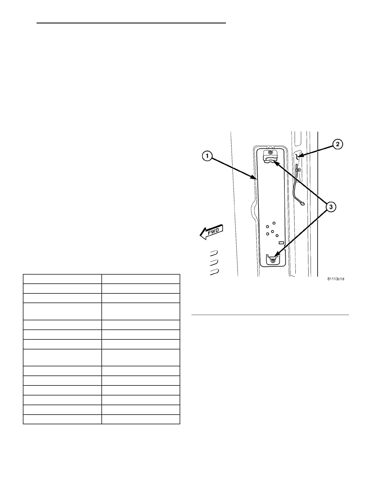
st raight ou t from the inner rear pilla r (Fig. 2).
(4) Pull the socket plat e a way fr om the in ner rear
pillar far enough to access t he backup la mp bulb
(Fig. 3).
Fig. 2 Tail Lamp Socket Plate Remove/Install
1 - SOCKET PLATE
2 - INNER REAR PILLAR
3 - LATCH TAB (2)
VA LAMPS/LIGHTING - EXTERIOR 8L - 5