(8) Position the front exhau st pipe aside.
(9) Lower th e vehicle.
(10) Remove the air cleaner housing h ose from t he
turboch arger and posit ion aside (Fig. 71).
(11) Remove t he turbocharger oil cooler lin es (Fig.
72).
(12) Remove the turbocharger to exha ust manifold
fasten ers and remove turboch arger (Fig. 72).
(13) Remove th e self locking exh aust ma nifold fas-
teners (Fig. 72).
(14) Remove exh aust ma nifold a nd clean mating
su rface.
INSTALLATION
NOTE: Exhaust manifold surface must be flat within
0.006 in. per foot (0.15mm per 300mm) of manifold
length.
(1) In spect exhaust manifold gasket surface for
flat ness wit h a straight edge.
(2) In spect exha ust manifold for cr acks or dist or-
tion.
(3) In st all new exhaust manifold gasket over the
studs.
(4) Position the exhaust man ifold over to st uds
and tight en reta ining nut s t o 30 N·m (22 lbs.ft.).
NOTE: Replace the turbocharger oil cooler line
banjo bolt seals before installing the oil cooler line.
(5) In st all turbocha rger (Refer to 11 - EXHAUST
SYSTEM/TURBOCHARGER SYSTEM/TURBO-
CHARGE R - INSTALLATION).
(6) Raise and support the vehicle.
(7) In st all the fr ont exh aust pipe t o turbocha rger
(Fig. 71).
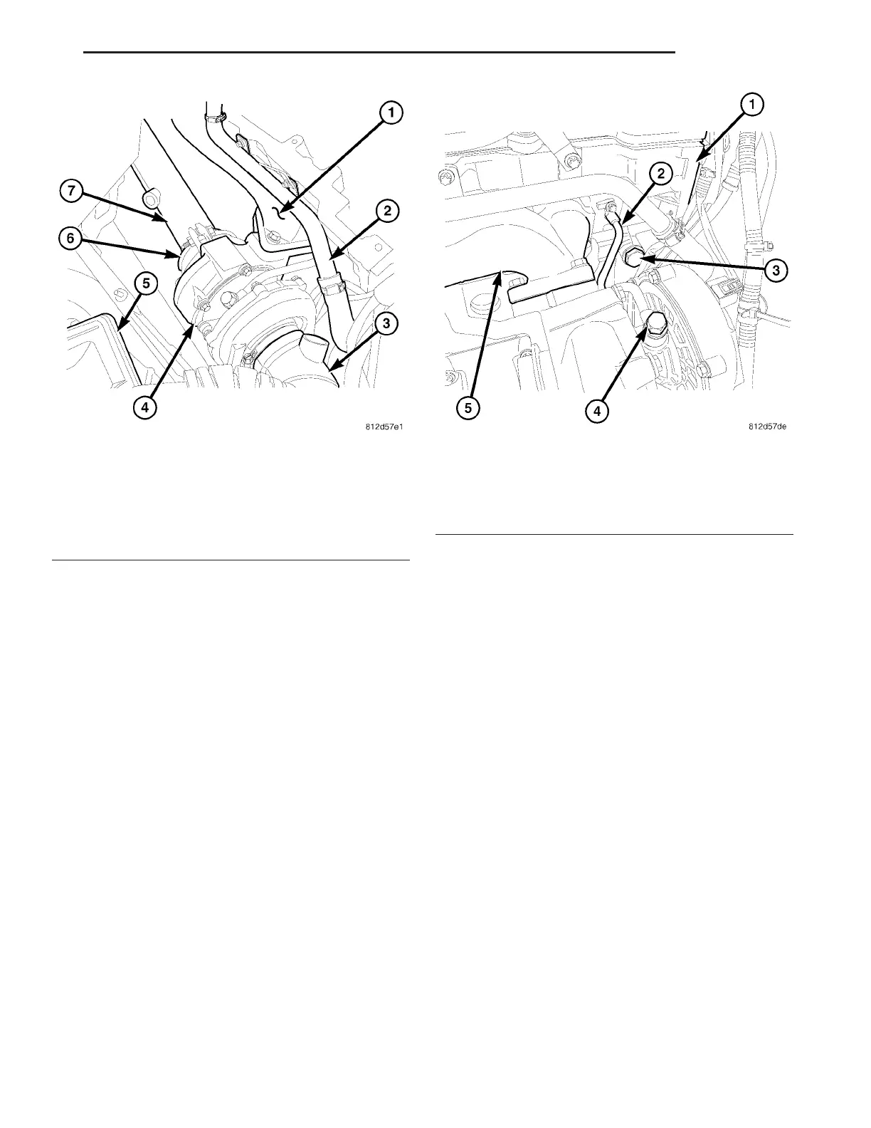
Fig. 71 TURBOCHARGER
1 - EXHAUST MANIFOLD
2 - HEATER PIPE
3 - AIR INLET TUBE
4 - TURBOCHARGER
5 - AIR CLEANER HOUSING
6 - EXHAUST CLAMP
7 - FRONT EXHAUST PIPE
Fig. 72 EXHAUST MANIFOLD
1 - CYLINDER HEAD
2 - TURBOCHARGER OIL COOLER LINE
3 - TIMING CHAIN TENSIONER
4 - BANJO BOLT
5 - EXHAUST MANIFOLD
VA ENGINE 9 - 69