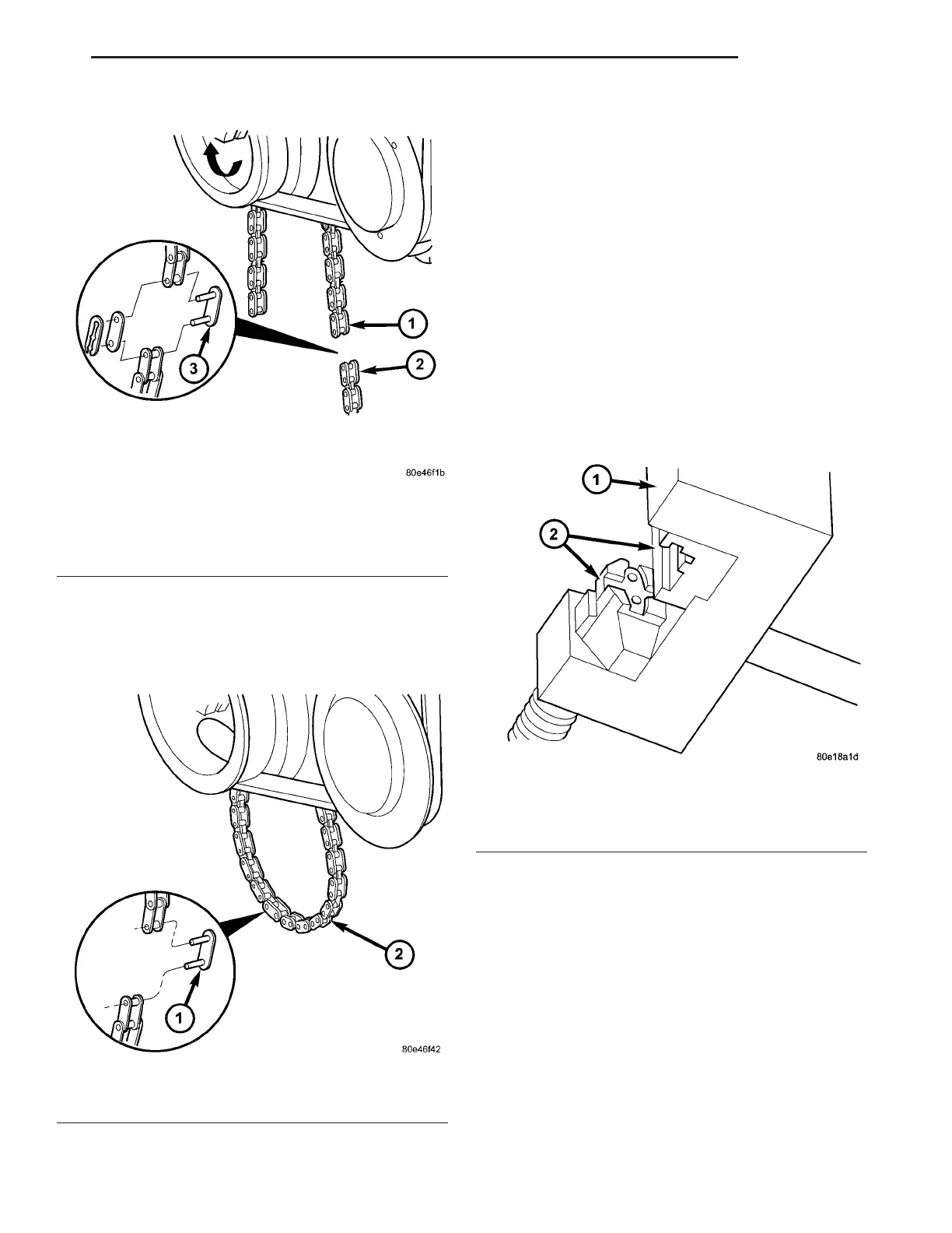
CAUTION: Insert new riveted link from the rear.
(4) Connect en ds of n ew oil pu mp ch ain wit h new
riveted link (Fig. 63).
NOTE: When assembling riveting tool, one piece is
secured by a screw and the other can move loosely
on the thrust spindle.
NOTE: The outer plate will be held in place by a
magnet.
(5) Pla ce new ou ter plate in to tool in ser t.
NOTE: Ensure that the riveted link and riveting tool
are aligned.
(6) Position rivet ing tool over new link an d pr ess
in new rivet as far as the tool stop.
(7) Remove riveting tool t o chan ge insert s.
(8) In st all in ser t on riveting tool and secu re with
scr ew.
(9) In st all inser t on rivetin g tool (Fig. 64).
NOTE: The outer plate is held in place magnetically
by riveting tool.
(10) Insert n ew outer plate into th e moving assem-
bly in ser t .
(11) Position riveting tool so tha t spacer webs of
the guide are side by side.
(12) Ensure that rivet ed link an d outer plate ar e
aligned.
NOTE: When turning spindle of riveting tool, be
sure that pins of riveted link are inserted into holes
of outer plate.
(13) Screw in spin dle of r ivet ing tool u ntil firm
resistance is felt.
Fig. 62 REMOVING OIL PUMP CHAIN TEMPORARY
LINK
1 - NEW OIL PUMP CHAIN
2 - OLD OIL PUMP CHAIN
3 - TEMPORARY LINK
Fig. 63 INSTALLING NEW RIVETED LINK
1 - NEW RIVETED LINK
2 - OIL PUMP CHAIN
Fig. 64 INSTALLING RIVETING INSERTS INTO
RIVETING TOOL
1 - SPECIAL TOOL #9312-1
2 - SPECIAL TOOL #9312-5 and #9312-9
VA ENGINE 9 - 63