First Gear Engaged
The TCM m onitor s the act iva tion sequence via t he
speed of th e inpu t shaft, which slows down as the
frictional con nection in the multiple-disc holding
clutch increases. When th e speed drops to t he speci-
fied level, the TCM sh uts off t he power to t he 3-4
sh ift solenoid valve (10) (Fig. 25). The sprin g cham-
ber of the shift valve B2 (9) is depressu rized a nd
switch es down wards. This connect s the line to t he
opposing face of the piston B2 (6) wit h the pressure
holding va lve (11). The pressure on the opposing face
of the piston B2 (6) drops to a residua l pressur e.
The working pressure (p-A) is form ed and tr avels
via t he 2-3 holding pr essu re shift valve, t he 2-3 com-
mand valve and the ball valve (16) to multi-plate
clutch K3 (4) an d via the 3-4 com mand valve (13) to
the end face of the 3-4 shift pressure shift valve (14).
The 3-4 shift pr essu re shift valve (14) is moved
aga inst the for ce of the spring towar ds the right. At
the sa me time th e 3-4 solenoid va lve (10) is ener-
gized. This allows sh ift valve pressure (p-SV) t o enter
the spring chamber of th e sh ift valve B2 (9) an d to
reach t he en d fa ce of t he 3-4 comma nd valve (13).
The shift valve B2 (9) is held in the upper position
and th e 3-4 comma nd valve (13) swit ches towa rds the
right. At the end face of t he 3-4 sh ift pressu re shift
valve (14) the working pressure (p-A) is replaced by
sh ift valve pr essu re (p-SV).
The 3-4 comma nd valve (13) moves to the left.
Working pressur e (p-A) tra vels via the h olding pres-
su re shift va lve (12) a nd the 3-4 command va lve (13)
to th e piston of m ultiple-disc holding clutch B2 (5).
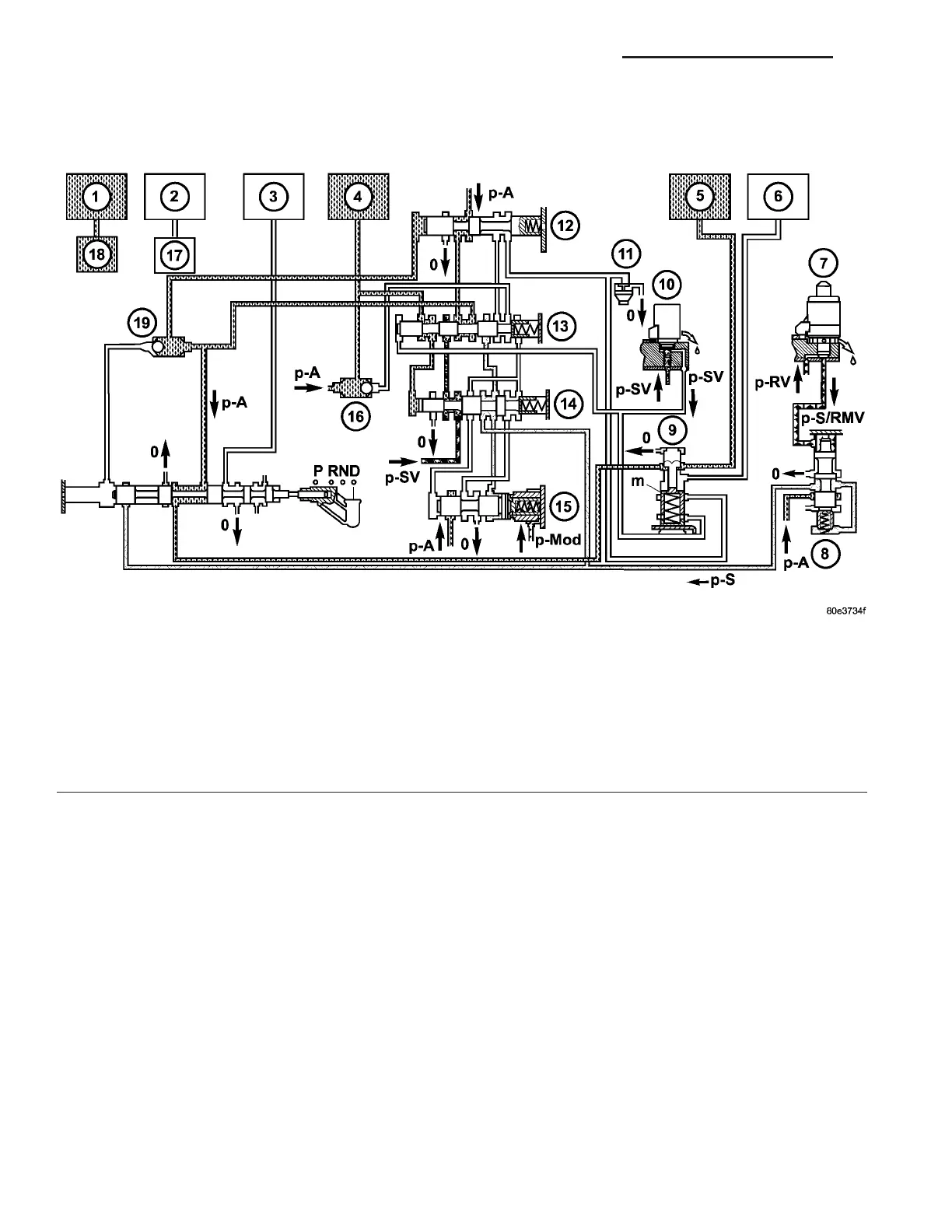
Fig. 25 First Gear Engaged
1 - HOLDING CLUTCH B1 11 - PRESSURE HOLDING VALVE
2 - DRIVING CLUTCH K1 12 - 3-4 HOLDING PRESSURE SHIFT VALVE
3 - HOLDING CLUTCH B3 13 - 3-4 COMMAND VALVE
4 - DRIVING CLUTCH K3 14 - 3-4 SHIFT PRESSURE SHIFT VALVE
5 - HOLDING CLUTCH B2 PISTON 15 - 3-4 OVERLAP REGULATING VALVE
6 - HOLDING CLUTCH B2 PISTON OPPOSING FACE 16 - BALL VALVE
7 - SHIFT PRESSURE REGULATING SOLENOID 17 - 1-2/4-5 COMMAND VALVE
8 - SHIFT PRESSURE REGULATING VALVE 18 - 1-2/4-5 COMMAND VALVE
9 - SHIFT VALVE B2 19 - BALL VALVE
10 - 3-4 SHIFT SOLENOID
21 - 38 AUTOMATIC TRANSMISSION NAG1 - SERVICE INFORMATION VA