OPERATION
Signals from the input speed sensors (6, 8) (F ig.
183) ar e recorded in th e transmission contr ol module
(TCM) togeth er with the wh eel a nd en gin e speeds
and other information and are processed int o an
input signa l for electron ic control.
In pu t speed sensor N2 (6) records the speed of th e
front su n gear via the externa lly toot hed disc car rier
of th e multiple-disc clutch K1 (10) and input speed
sensor N3 (8) records the speed of the front planet
carrier v ia th e in tern ally toothed disc carrier of m ul-
tiple-disc clutch K1 (3).
OI L PU M P
DESCRIPTION
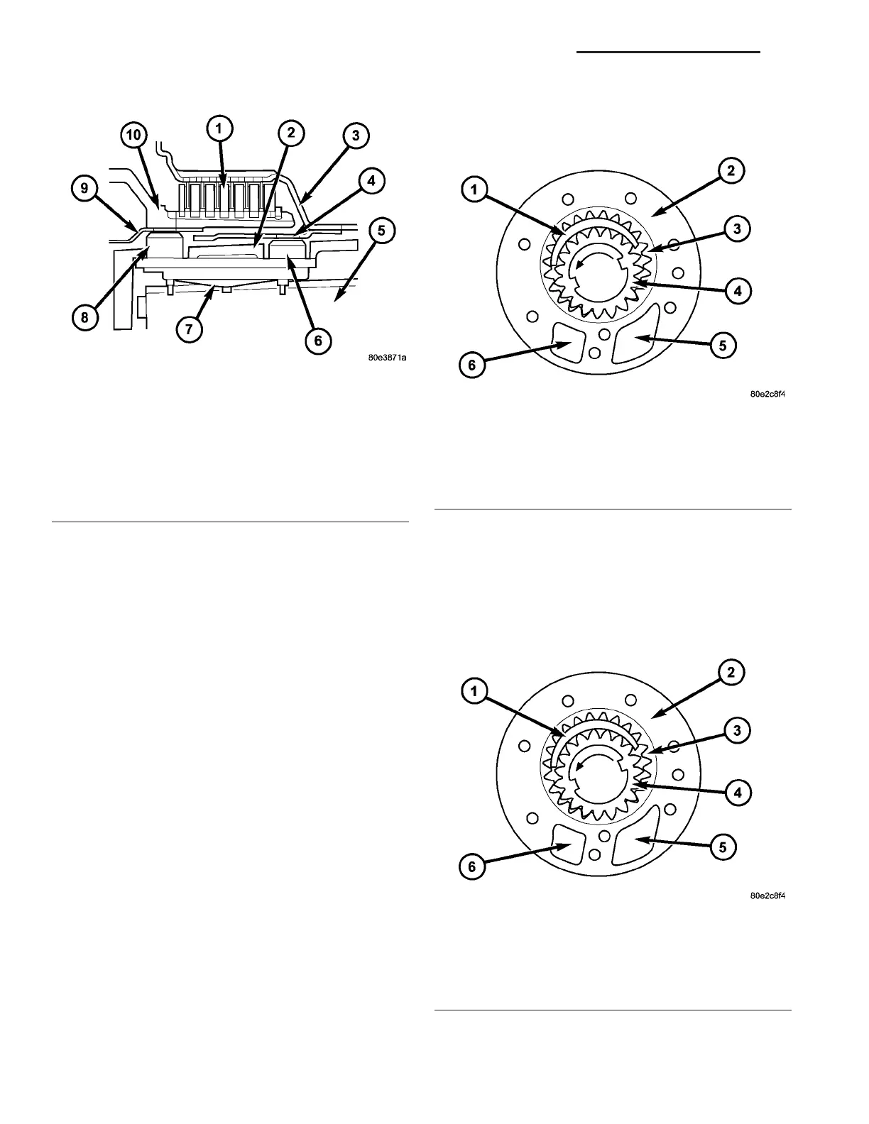
The oil pump (2) (Fig. 184) (crescen t-type pu mp) is
insta lled in the bellhou sing behind t he t orque con-
vert er a nd is driven by th e drive flange of the tor que
conver ter. Th e pu mp creates the oil pressure required
for the h ydrau lic pr ocedu res.
OPERATION
When th e engine is run ning, th e oil (Fig. 185) is
pu mped through the inlet chamber (5) a long th e
Fig. 183 Input Speed Sensors
1 - DRIVING CLUTCH K1
2 - TRANSMISSION HOUSING
3 - DRIVING CLUTCH K1 INTERNALLY TOOTHED DISC
4 - EXCITER RING
5 - VALVE HOUSING OF SHIFT PLATE
6 - N2 INPUT SPEED SENSOR
7 - SPRING
8 - N3 INPUT SPEED SENSOR
9 - EXCITER RING
10 - DRIVING CLUTCH K1 EXTERNALLY TOOTHED DISC
Fig. 184 Oil Pump
1 - CRESCENT
2 - OIL PUMP
3 - EXTERNAL GEAR
4 - INTERNAL GEAR
5 - INLET CHAMBER
6 - PRESSURE CHAMBER
Fig. 185 Oil Pump
1 - CRESCENT
2 - OIL PUMP
3 - EXTERNAL GEAR
4 - INTERNAL GEAR
5 - INLET CHAMBER
6 - PRESSURE CHAMBER
21 - 154 AUTOMATIC TRANSMISSION NAG1 - SERVICE INFORMATION VA