Radia l runou t of more than 1.5 mm (.060 inch)
measu red at the cent er line of t he tread may cause
the vehicle t o shake.
Lateral run out of more than 2.0 mm (.080 inch)
measu red nea r the sh oulder of th e t ire may cause t he
vehicle to sha ke.
Som etim es radia l runout ca n be reduced. Reloca te
the wheel a nd t ire assem bly on th e mount ing studs
(See Method 1). If this does not reduce runout to a n
accepta ble level, the tire can be r otated on the wheel.
(See Meth od 2).
METHOD 1 (RELOCATE WHEEL ON HUB)
(1) Drive vehicle a short dist ance to elim ina te tire
flat spott ing from a parked position.
(2) Check wheel bea rings and adjust if adjusta ble
or replace if necessa ry.
(3) Check the wh eel m ounting su rface.
(4) Relocate wheel on the mou nting, two studs
over from the original position.
(5) Tighten wheel nu ts until a ll are proper ly
torqu ed, to eliminat e bra ke distortion.
(6) Check radia l ru nout. If st ill excessive, mar k
tire sidewall, wh eel, and stu d a t point of maximum
runout and proceed to Method 2.
METHOD 2 (RELOCATE TIRE ON WHEEL)
NOTE: Rotating the tire on wheel is particularly
effective when there is runout in both tire and
wheel.
(1) Remove tire from wh eel an d mou nt wh eel on
service dyn amic balance mach ine.
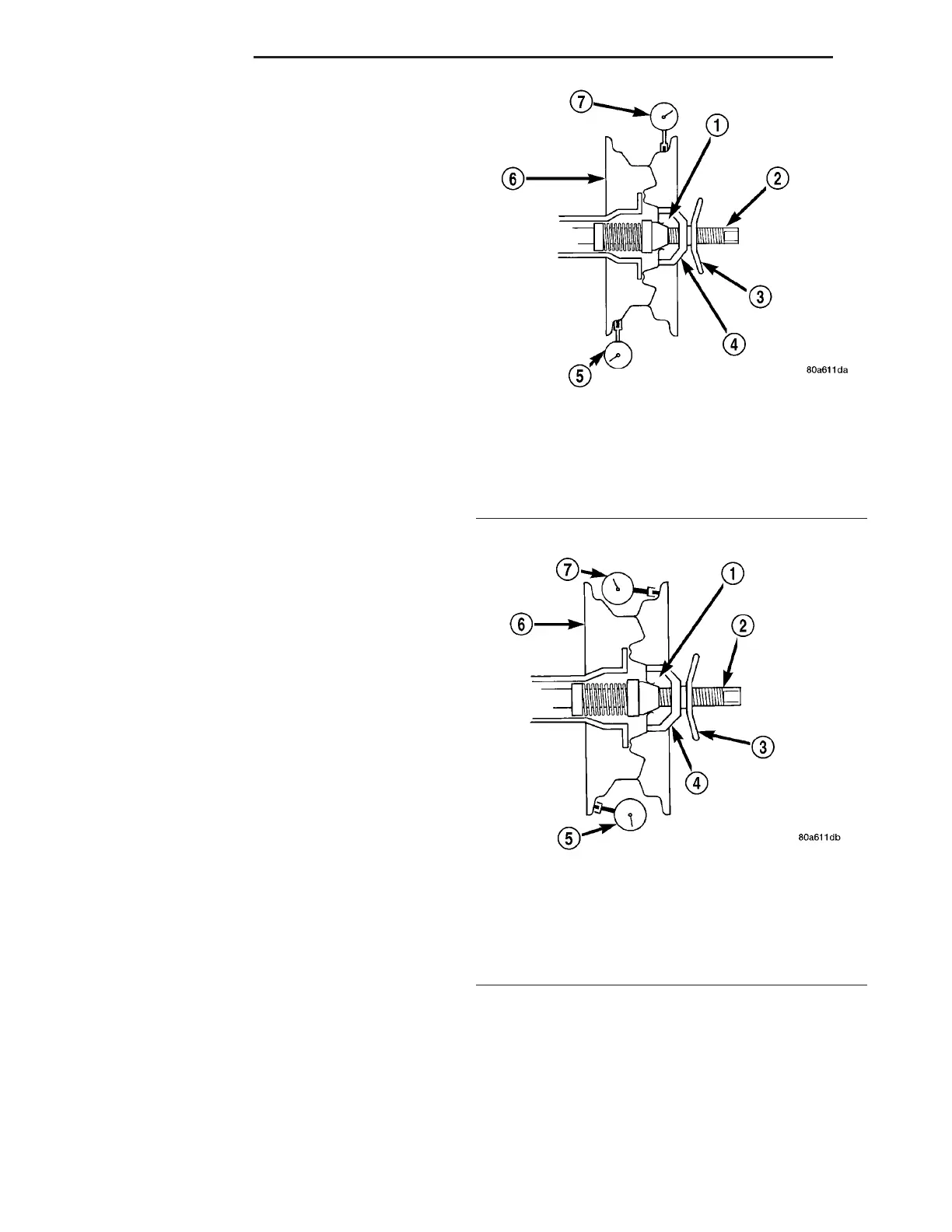
(2) Check wheel radial run out (Fig. 2) and later al
runout (Fig. 3).
• STE EL WHEELS: Radial runout 0.031 in., Lat-
eral runout 0.031 in. (maximu m)
• ALUMINUM WH EELS: Radial runou t 0.020 in.,
Lateral runout 0.025 in. (maximum)
(3) If poin t of great est wheel la tera l runout is near
origina l chalk mark, rem ount tire 180 degr ees.
Recheck ru nout, Refer to ma tch m ounting pr oce-
dure.
STAN DARD PROCEDU RE
STANDARD PROCEDURE - MATCH MOUNTING
Wheels an d tir es are match mou nted a t the factory.
This mean s tha t the high spot of t he t ire is matched
to the low spot on th e wh eel r im. Each a re mar ked
with a bright colored tempora ry label on the out-
board sur face for align ment . Th e wheel is also
Fig. 2 Radial Runout
1 - MOUNTING CONE
2 - SPINDLE SHAFT
3 - WING NUT
4 - PLASTIC CUP
5 - DIAL INDICATOR
6 - WHEEL
7 - DIAL INDICATOR
Fig. 3 Lateral Runout
1 - MOUNTING CONE
2 - SPINDLE SHAFT
3 - WING NUT
4 - PLASTIC CUP
5 - DIAL INDICATOR
6 - WHEEL
7 - DIAL INDICATOR
22 - 2 TIRES/WHEELS VA