(1) Raise and support the vehicle.
(2) Position a suitable lifting device u nder t he a xle
and secure axle t o device.
(3) Remove wheels an d t ires.
(4) Unplug wear indica tor cable (Fig. 2) and (Fig.
3).
(5) Detach cable connect or for brake pad wear
indicator.
(6) Remove ABS sen sor and clam p bu sh ing from
mounting bore.
NOTE: The right-hand ABS sensor cable is labeled
at the factory with a white tag.
(7) Remove cable t ies from the park br ake cables.
Relea se connection cable of brake pad wear indica tor
and ABS sensor cable up to th e relay unit of the
parking bra ke.
(8) Remove bra ke ca bles.
(9) Remove hand brake cable at r elay un it.
(10) Remove bracket for brake cables a t rea r axle
tube.
(11) Remove stabilizer bar from axle brackets.
(12) Remove shock absorber bolts fr om rear axle.
(13) Remove ALB lever from rea r axle bra cket.
(14) Pull vent line of rea r axle out of fr ame.
(15) Remove propeller sha ft.
(16) Remove brake calipers.
(17) Remove U-bra cket s and plates (F ig. 2) and
(Fig. 3).
(18) Remove axle fr om the vehicle.
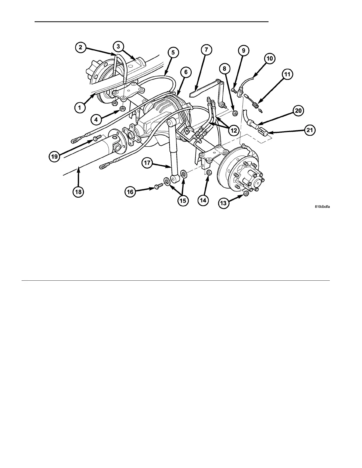
Fig. 3 DUAL REAR WHEEL AXLE
1 - SPRING 12 - BRAKE HOSE
2 - SPRING SHACKLE 13 - LUG NUT
3 - PLATE 14 - NUT
4 - COLLAR NUT 15 - WASHER
5 - BRAKE CABLE 16 - BOLT
6 - REAR AXLE 17 - SHOCK ABSORBER
7 - ALB LEVER 18 - PROPELLER SHAFT
8 - NUT 19 - BOLT
9 - BOLT 20 - ABS SENSOR
10 - WEAR INDICATOR CABLE 21 - SENSOR BUSHING
11 - WEAR INDICATOR CONNECTOR
VA REAR AXLE 3 - 15