(1) Raise axle in to position.
(2) In st all plates and U-bra cket s (Fig. 4) an d (Fig.
5) wit h new nu ts. Tigh ten nu ts to 170 N·m (125 ft.
lbs.).
(3) In st all pr opeller sh aft and tighten bolt s to 70
N·m (52 ft. lbs.).
NOTE: On installation of the propeller shaft, joint
arrows must be flush and must point towards the
frame floor. Tighten the propeller shaft in this posi-
tion.
(4) In st all ALB lever to axle bra cket and tight en
new nu t 34 N·m (46 ft. lbs.).
(5) In st all shock a bsorber s to rear axle an d tighten
bolts t o:
• M12 x 1.5 Bolt - 70 N·m (52 ft. lbs.)
• M14 x 1.5 Bolt - 110 N·m (81 ft. lbs.)
(6) In st all stabilizer bar to axle a nd tight en bolts
to:
• SRW Axle - 25 N·m (18 ft. lbs.)
• DRW Axle - 70 N·m (52 ft . lbs.)
(7) In st all calipers with adapter s a nd lines.
(8) In st all bra ke hoses a nd hold-down clips.
(9) In st all and a djust park br ake cables.
(10) Install connection cable of brake pad wea r
indicator and ABS sensor cable up to the rela y unit
of the parkin g bra ke.
(11) In st all cable ties to t he par k br ake cables.
(12) Install ABS sen sor and clamp bushing to
mounting bore.
NOTE: The right-hand ABS sensor cable is labeled
at the factory with a white tag.
(13) Atta ch connector cable for br ake pad wea r
indicator.
(14) Plu g in ca ble of brake pad wear in dicator.
(15) Install the wheels an d tires.
(16) Fill a xle with a ppropriate lubrica nt.
(17) Remove lifting device from under the axle.
(18) Remove support a nd lower vehicle.
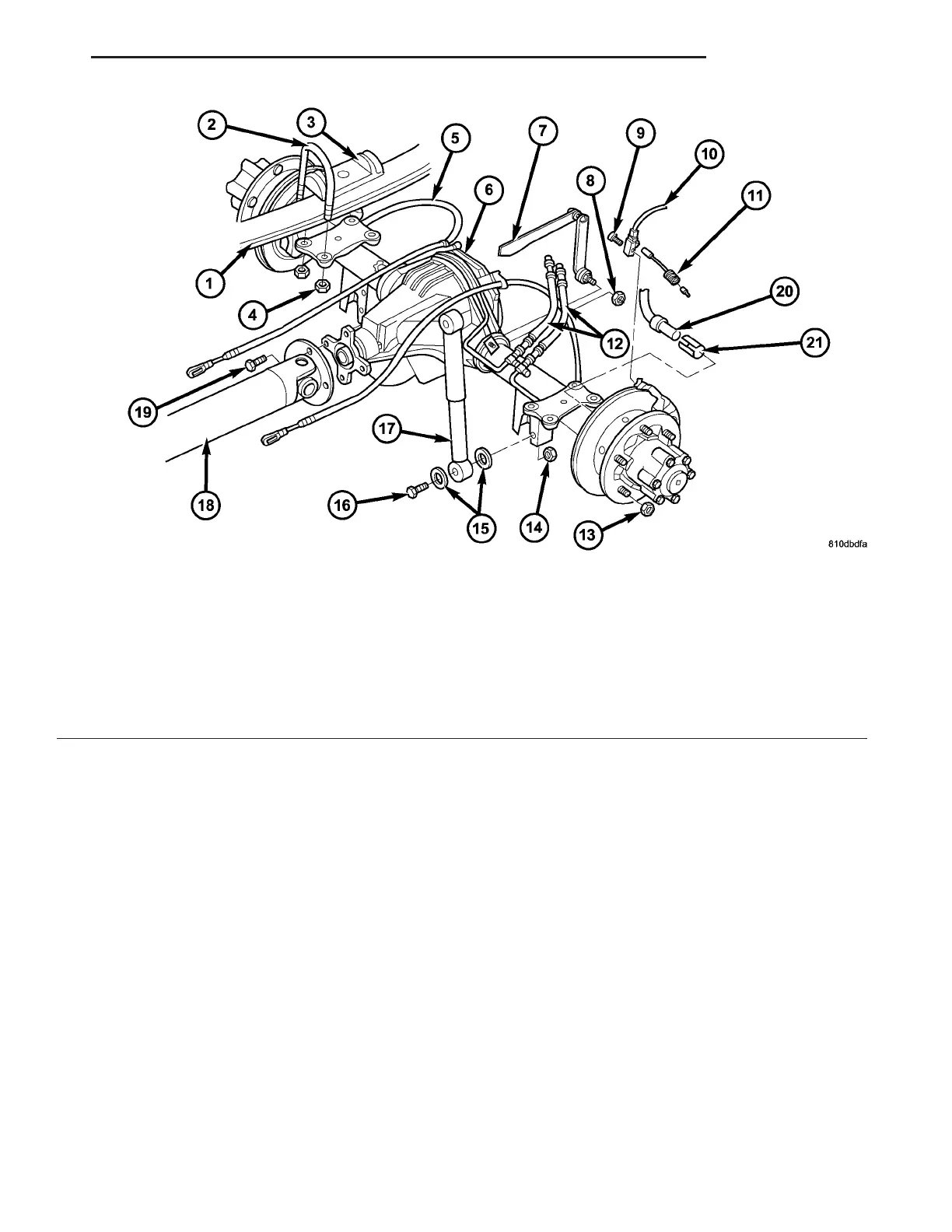
Fig. 5 DUAL REAR WHEEL AXLE
1 - SPRING 12 - BRAKE HOSE
2 - SPRING SHACKLE 13 - LUG NUT
3 - PLATE 14 - NUT
4 - COLLAR NUT 15 - WASHER
5 - BRAKE CABLE 16 - BOLT
6 - REAR AXLE 17 - SHOCK ABSORBER
7 - ALB LEVER 18 - PROPELLER SHAFT
8 - NUT 19 - BOLT
9 - BOLT 20 - ABS SENSOR
10 - WEAR INDICATOR CABLE 21 - SENSOR BUSHING
11 - WEAR INDICATOR CONNECTOR
VA REAR AXLE 3 - 17