rate and boost pressure are a djust ed to the actual
injection qua ntity.
• Injection valve quan tity drift compen sa tion in
full load range: t his fu nction is to limit t he maximum
injection quan tity for engine protection . The injection
quan tity signal is compar ed t o the injection qu antity
calcu lated from th e oxygen sensor sign al a nd MAF
signal. If the comparison sh ows that the a ctual injec-
tion quan tity is too high, it is lim ited to th e maxi-
mum permissible in ject ion qua ntity
• Air-fu el r atio con trolled sm oke limit er (fu ll loa d):
the smoke limiter limits the injection qua ntity on t he
basis of the air-fuel ratio permissible a t t he smoke
lim it depen ding on t he measure mass air fl ow a nd
the calcula ted EGR rate. As a consequence, the gen-
erat ion of sm oke due t o an excess injection qu ant ity
is avoided under all oper ating condition s. At the
sa me time, the oxygen sensor signal is used to
ensure tha t the a ir-fu el ratio is adjusted a ccordingly
A fu nction r eferred to as air flow sensor drift com-
pensation detect s a nd corrects the possible driftin g of
the MAF sensor by comparing th e air ma ss m easured
by t he MAF with t he projected air mass as it is cal-
cula ted by the ECM in consideration of various in flu-
encin g condition s. It is the air flow dr ift
compensation t hat gives the MAF air m ass measure-
ment the precision needed to use it for the funct ion
ment ioned a bove. The high precision of t he MAF
measu remen t enables the ca lculation of th e actual
injection quantity from the mea su red air mass and
from the oxygen sen sor signa l in order to corr ect
injection quan tit y. The MAF signal can also be used
as a input par amet er for the sm oke limiter.
REMOVAL
(1) Disconn ect the n egat ive battery cable.
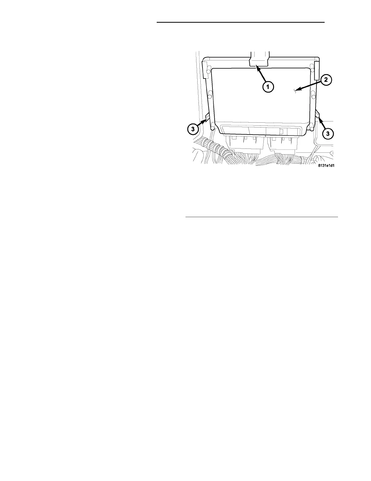
(2) Disconn ect the ECM ha rness connectors (F ig.
4).
(3) Grasp ECM and pull down firmly t o release
ECM from t he retaining bra cket tensionin g springs
(Fig. 4).
INSTALLATION
NOTE: THE ECM MUST BE PROGRAMMED TO SUP-
PORT THE VEHICLE OPTIONS PACKAGE.
(1) Position t he ECM in to the gu ide of t he retain-
ing bra cket (Fig. 4).
(2) Carefully push t he ECM in t o the bracket u ntil
the bracket tensioning spr ings engage (Fig. 4).
(3) Connect the ECM wiring harness con nector s
(Fig. 4).
(4) Connect nega tive bat tery cable.
TRANSMISSION CONTROL
MODULE
DESCRIPTION
The transm ission control module (TCM) receives,
pr ocesses and sen ds various digital and analog sig-
nals related to the automatic transmission. In addi-
tion, it processes information r eceived from oth er
vehicle system s, such as engine tor que and speed,
accelerat or pedal position, wh eel speed, kick-down
switch , tra ction cont rol inform ation, et c.
The TCM is locat ed un der the dr iver ’s sea t and is
connect ed to oth er control modules via a CAN bus. It
controls all shift functions to ach ieve smoot h sh ift
comfort in all driving situ ations considerin g:
• Vehicle speed.
• Tra nsmission status.
Fig. 4 ECM
1 - BRACKET
2 - ECM
3 - BRACKET TENSIONING SPRINGS
8E - 6 ELECTRONIC CONTROL MODULES VA