INSPECTION
The following inform ation det ails th e recommen ded
inspection procedu res for th e ba tter y and related
components. In a ddition to the mainten ance sched-
ules found in this service ma nua l and the owner’s
manual, it is recom mended that t hese pr ocedu res be
performed any time th e ba tter y or related compo-
nent s m ust be removed for vehicle ser vice.
(1) In spect t he ba tter y cable ter minal clamps for
da mage. Replace any ba tter y cable that has a dam-
aged or defor med ter min al clamp.
(2) In spect the battery tr ay a nd batt ery holddown
hardwa re for dam age. Replace any damaged par ts.
(3) Slide th e thermal guard off of the battery case,
if equipped. In spect the battery case for cracks or
other dam age t hat cou ld result in electrolyt e leaks.
Also, ch eck the ba tter y term inal posts for looseness.
Batt eries wit h damaged ca ses or loose t erminal posts
must be r eplaced.
(4) In spect the bat tery th erma l guar d for tears,
cracks, deform ation or ot her dama ge. Replace a ny
ba t t er y t h er m a l gu a r d t h a t h a s been da m a ged.
(5) In spect t he batter y bu ilt -in test indica tor sight
gla ss for an indication of t he batter y condition. If the
batt ery is disch arged, cha rge as requir ed. (Refer to 8
- ELECTRICAL/BATTERY SYSTE M/BATTERY -
STANDARD PROCE DURE ).
SPECI AL T OOLS
BATTERY SYSTEM SPECIAL TOOLS
BAT T ERY
DESCRIPTION
Large capacity, low-mainten ance storage bat teries
are st andar d factory-insta lled equipment on th is
model. Th e pr imary bat tery i s located in the en gine
compart ment on all models. A second a uxiliary ba t-
tery ma y be installed under th e passengers fr ont sea t
for runn ing addit ional electrical equipment .
Male post type term ina ls made of a soft lead ma te-
ria l protrude from t he top of the molded pla st ic bat-
tery case to provide th e means for connectin g th e
batt ery to th e vehicle electr ical system . The ba tter y
positive terminal post is physically larger in diam eter
than th e negat ive ter minal post to en su re proper bat-
tery connection. The lett ers POS and NEG are also
molded in to th e top of th e bat tery case a djacen t to
their r espective positive and negative ter min al posts
for iden tification confirma tion. Refer to Batt ery
Cables for more inform ation on the battery cables
that con nect the ba tter y to th e vehicle electrical sys-
tem.
The ba tter y is ma de up of six individual cells that
are conn ected in series. E ach cell cont ains positively
charged plat e gr oups that are conn ected with lead
st raps to the positive ter minal post, and negatively
charged plat e gr oups that are conn ected with lead
st raps t o the nega tive t erminal post. Ea ch plate con-
sists of a stiff mesh fram ework or grid coated with
lead dioxide (posit ive pla te) or sponge lead (negat ive
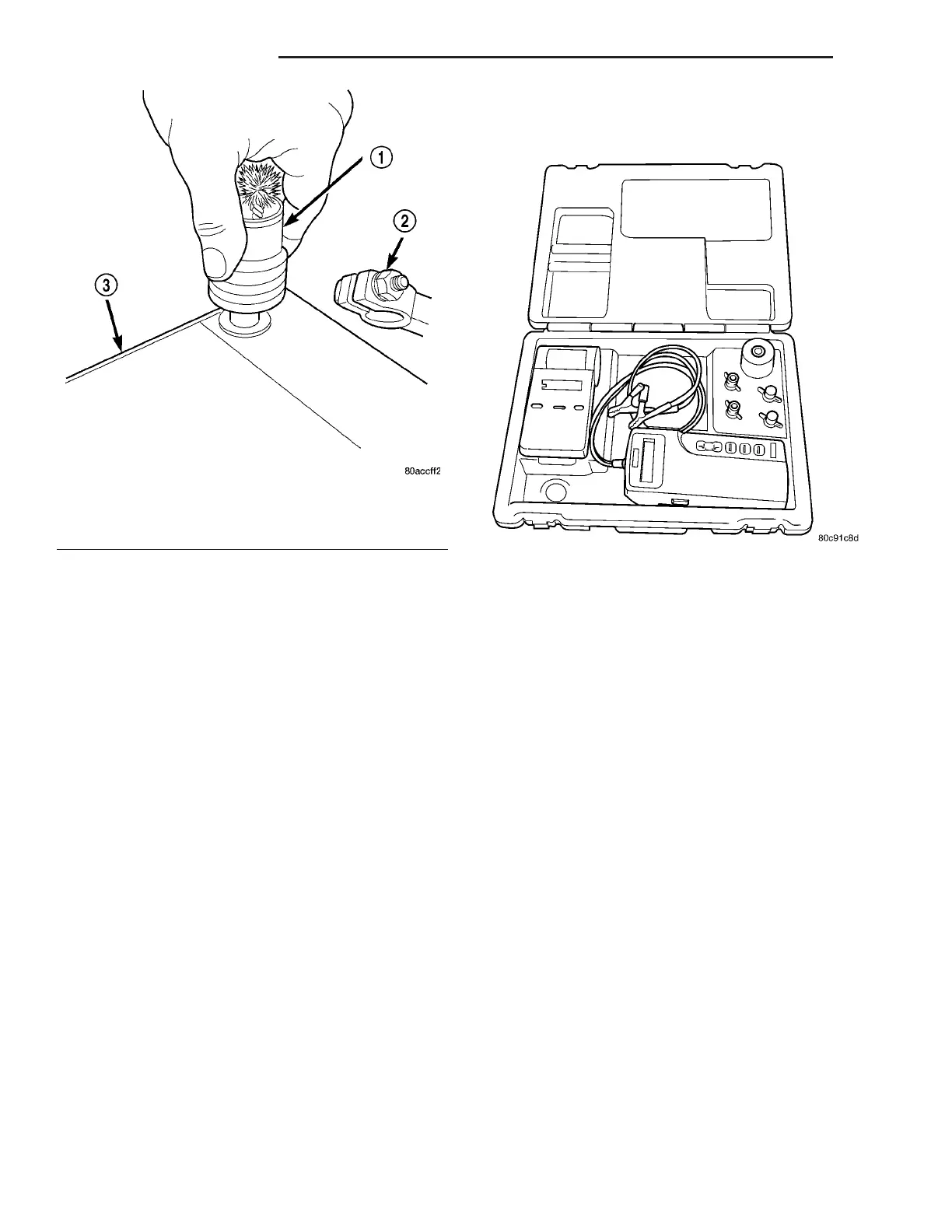
Fig. 3 Clean Battery Terminal Post - Typical
1 - TERMINAL BRUSH
2 - BATTERY CABLE
3 - BATTERY
Micro 420 Battery Tester
8F - 6 BAT T ER Y S Y S T EM VA