POWER WI N DOWS
TABLE OF CONTENTS
page page
POWER WINDOWS
DESCRIPTION ..........................5
OPERATION ............................5
WINDOW MOTOR
REMOVAL .............................5
POWER WINDOW SWITCH
DIAGNOSIS AND TESTING - POWER
WINDOW SWITCH ......................5
REMOVAL .............................5
INSTALLATION ..........................6
POWER WI N DOWS
DESCRIPTION
The power window system allows each of th e door
windows to be ra ised an d lowered electrically by
actuatin g a switch on each door panel. A master
switch on the dr iver s door allows the dr iver to ra ise
or lower each door window. The power window sys-
tem opera tes only wh en the ign ition switch is in the
RUN or ACCESSORY position .
OPERATION
WINDOW SWITCH
The power window switches con trol th e ba ttery
and gr ound feeds to the power window motors. The
pa ssen ger door power win dow switch es receive their
batt ery and ground feeds through t he circuitry of t he
dr iver s window switch .
WINDOW MOTOR
Window m otors use perm anen t t ype ma gnet s. The
B+ a nd grou nd applied at the motor terminal pins
will cause the motor to r otate in one direction .
Rever sing cu rren t through the mot or t erminals will
cause t he mot or to rot ate in the opposite direction.
Refer to th e appropriate wirin g informat ion. Th e
wiring information includes wir ing dia gra ms, proper
wire a nd connector repair procedu res, details of wire
harness routing and ret ention, connector pin-out
information and loca tion views for th e various wire
harness connectors, splices an d grounds.
WI N DOW M OT OR
REMOVAL
The window motor is ser viced with th e window
regu lat or.
POWER WI N DOW SWI T CH
DIAGNOSIS AND TESTING - POWER WINDOW
SWITCH
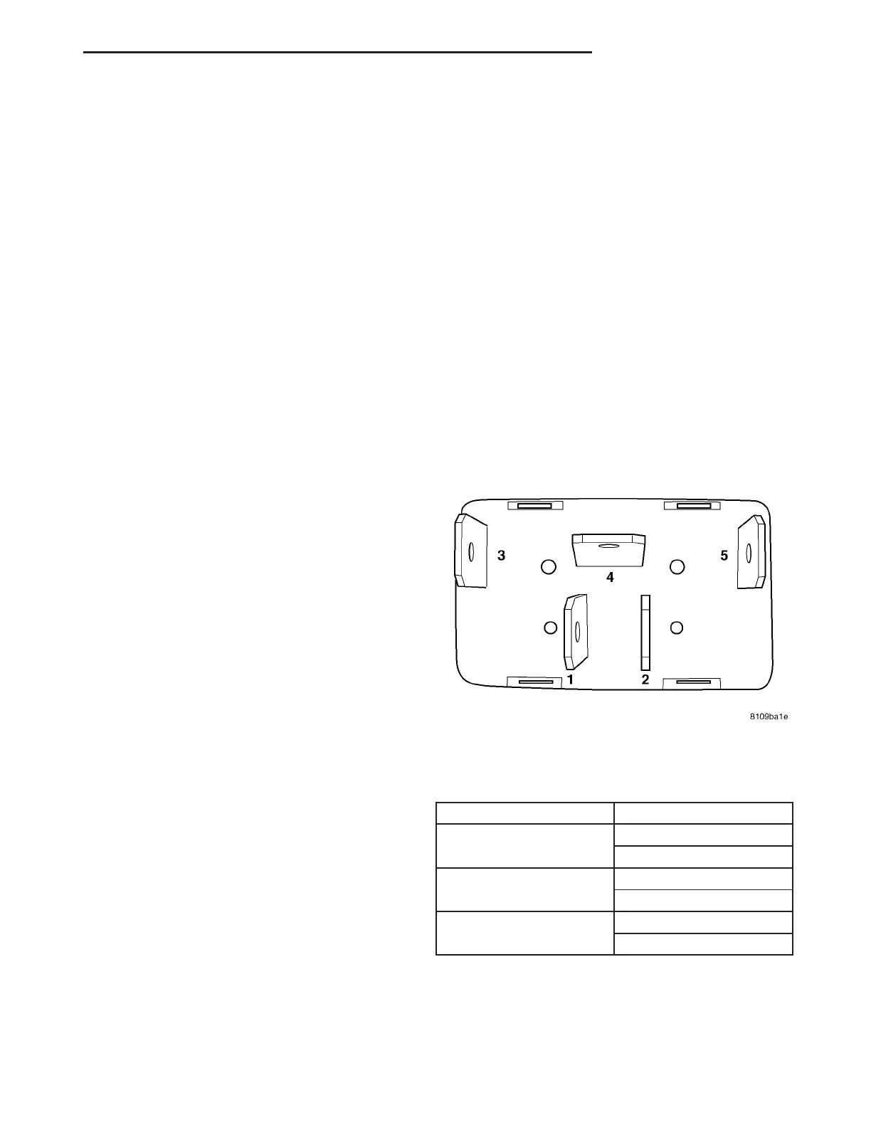
Test the power win dow switch con tinu ity. Refer to
the Power Window Swit ch Con tinuity char t to deter-
mine if the contin uity is correct in the Off, Up and
Down switch posit ions (Fig. 1).
POWER WI N DOW SWI T CH CON T I N U I T Y
CH ART
SWITCH POSITION CONTINUITY BETWEEN
UP PIN 1 AND 3
PIN 2 AND 4
DOWN PIN 1 AND 4
PIN 2 AND 5
NEUTRAL (OFF) PIN 1AND 3
PIN 2 AND 5
REMOVAL
(1) Disconn ect and isolate the battery nega tive
cable.
(2) Remove door han dle cover.
Fig. 1 POWER WINDOW SWITCH
VA POWER WINDOWS 8N - 5