Repairing/Replacing Internal Components
9-10 DSX™ System Service Manual
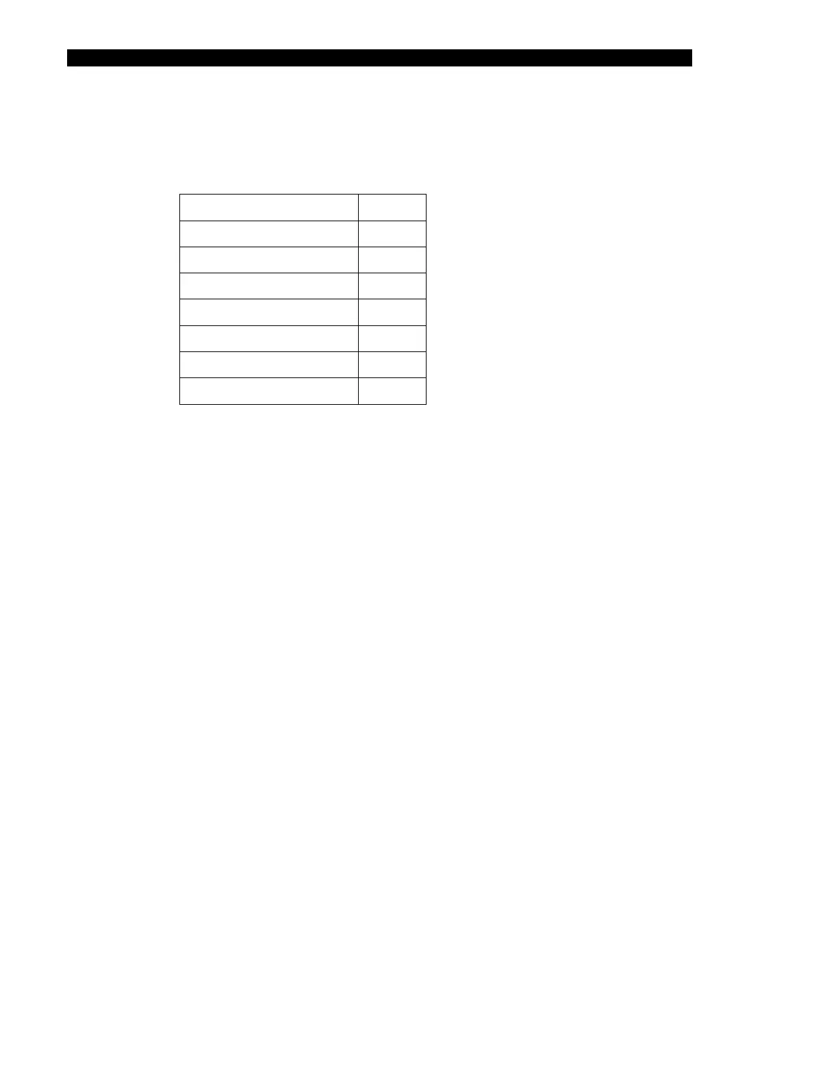
To Remove the Main Board:
1 Disconnect the connectors from the board.
Fan (where installed)
J1
LED (where installed)
J3
Heater (Carrier)
J4
Power Connector
J5
Heater (Top)
J6
Motor
J7
Home Sensor
J8
Eject Sensor
J9
2 Unfasten the board by removing the 4 M3 x 8 mm socket head cap screws and
M3 lock washers.
3 Lift the board off of the standoffs.
To Install the Main Board:
1 Installation is the reverse of the removal procedure.
2 After installation, the module must be tested and calibrated using DynexTest
software and a calibrated thermometer.