Design of the Optical Module
10-2 DSX™ System Service Manual
10.2.2 Optical Considerations
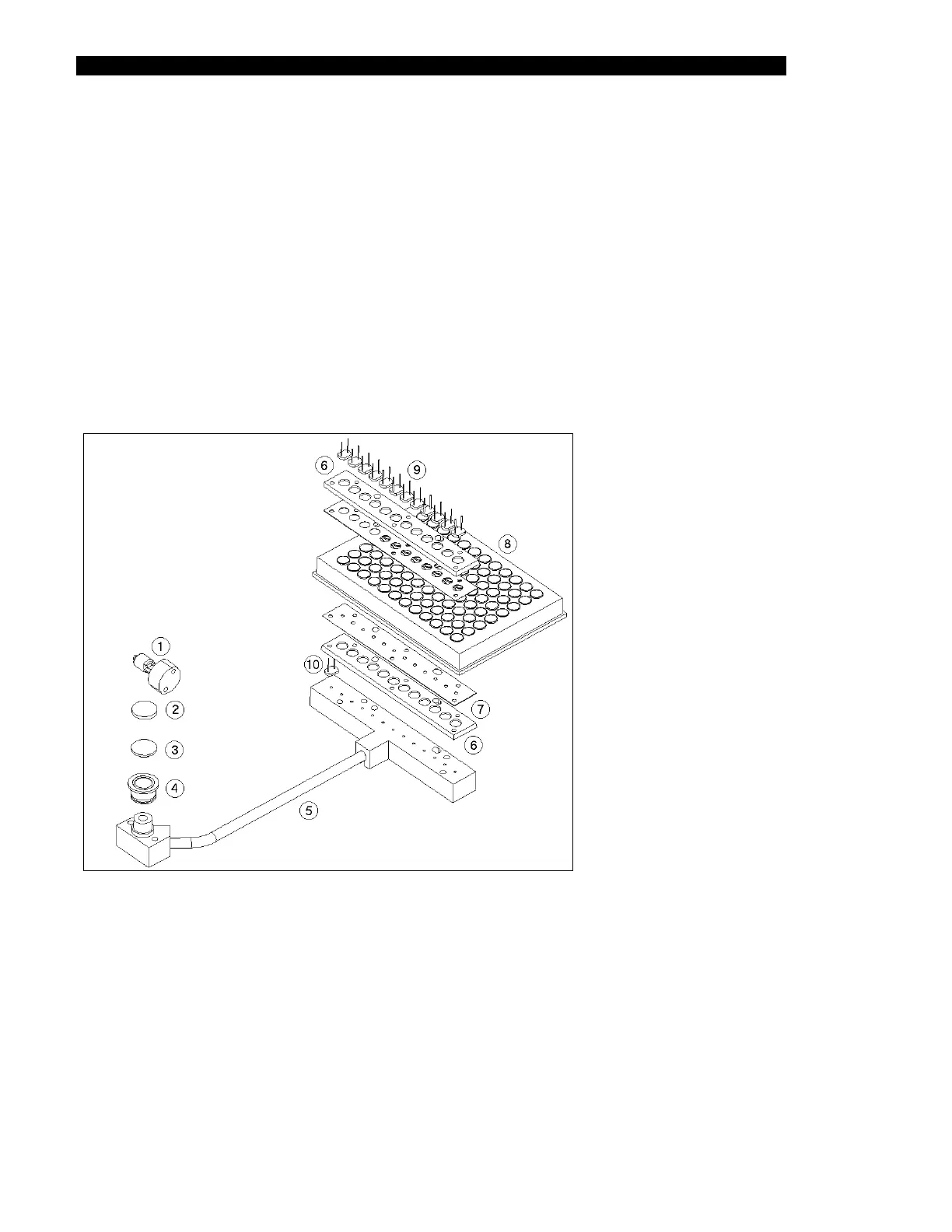
A schematic diagram illustrating the optical path through the Reader Module is presented in
Figure 10-1. A tungsten halogen lamp projects a light beam vertically through a heat-
absorbing filter. This beam is focused by an aspheric lens and passes through a bandpass filter
located in the filter wheel. The filters exclude all light with the exception of the desired
wavelength. The beam is then separated into 13 channels; one of these channels is used as a
reference channel to monitor the light output of the lamp while the other 12 beams are
directed upwards through a row of 12 wells on the microplate onto an array of silicon
photodiodes. The silicon photodiodes quantify the intensity of light transmitted through the
cells in a row of the well plate solution. The transmittance of each solution is thus measured,
compared to the signal of the reference channel and the concentration of the compound of
interest can be determined.
1 Lamp 6 Lenses
2 Heat Filter 7 Optic Stops
3 Lens 8 Microplate
4 Filter 9 Photodiodes
5 Optic Fibers 10 Reference
Diode
Figure 10-1 Optical Path