Repairing/Replacing Internal Components
13-20 DSX™ System Service Manual
13.4.3 Replacing the Printed Circuit Board Assembly
There are two printed circuit boards in the Washer Module, a daughter board and the main
board. The daughter board is attached to the main board by pressing it into the mating
connector and securing it to the standoffs with three M3 x8 Cap Head Screws and 3 nylon
washers.
To Replace the Printed Circuit Board Assembly:
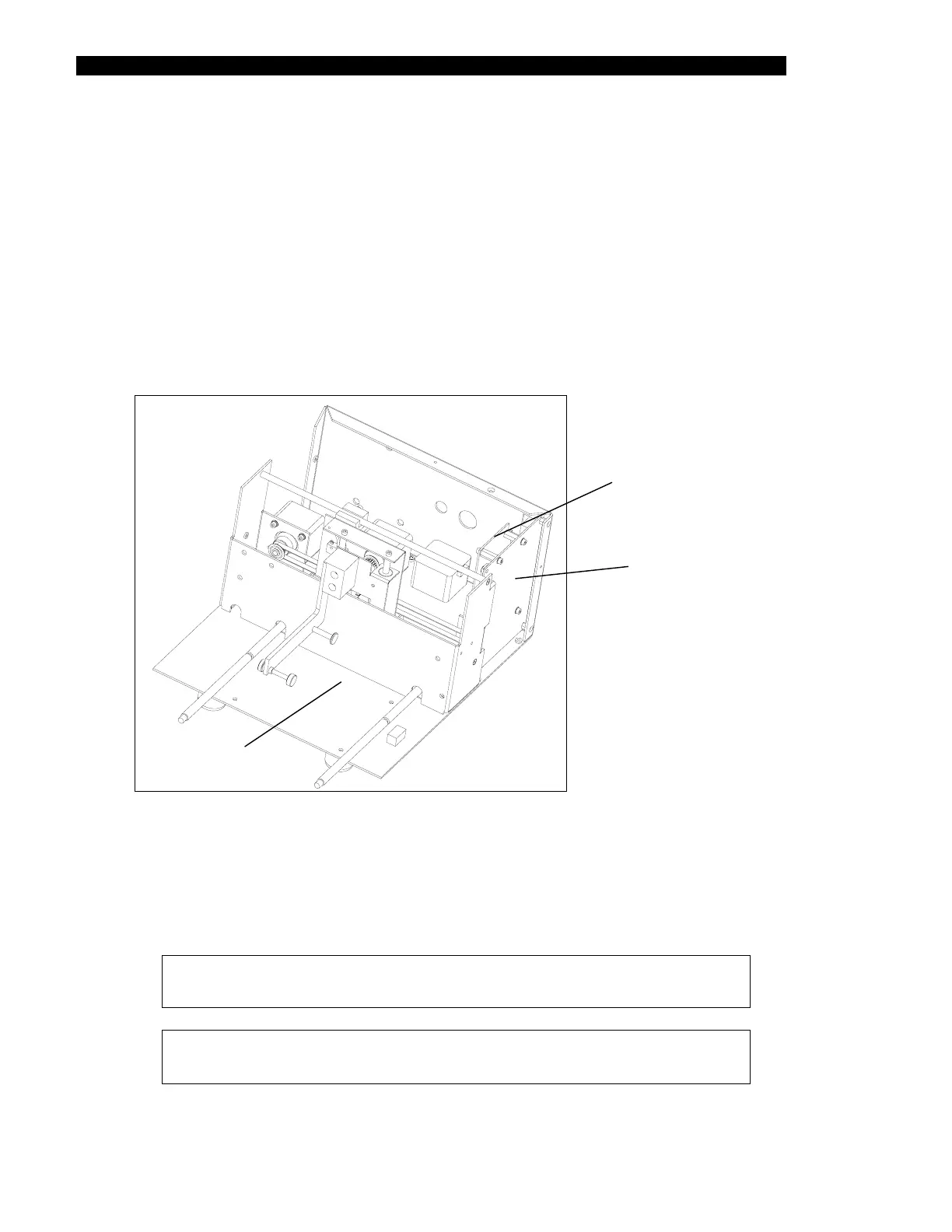
1 Remove the two screws and Nylon washers that secure the assembly to the PCB
mounting bracket (Figure 13-12)
PCB Assembly
PCB Mounting
Bracket
Main Assembly
Figure 13-12 Printed Circuit Board and PCB Bracket
2 Remove the screw and Nylon washer that secures the assembly to the front
mounting bracket.
3 Replace the PCB by reversing the disassembly proedure
Note: When replacing the screws, secure them with Loctite 222.
Note: When replacing the main pcb, it must be calibrated using
DynexTest software and the Dynex Washer Calibration Software.