Replacing External Components
DSX™ System Service Manual 13-15
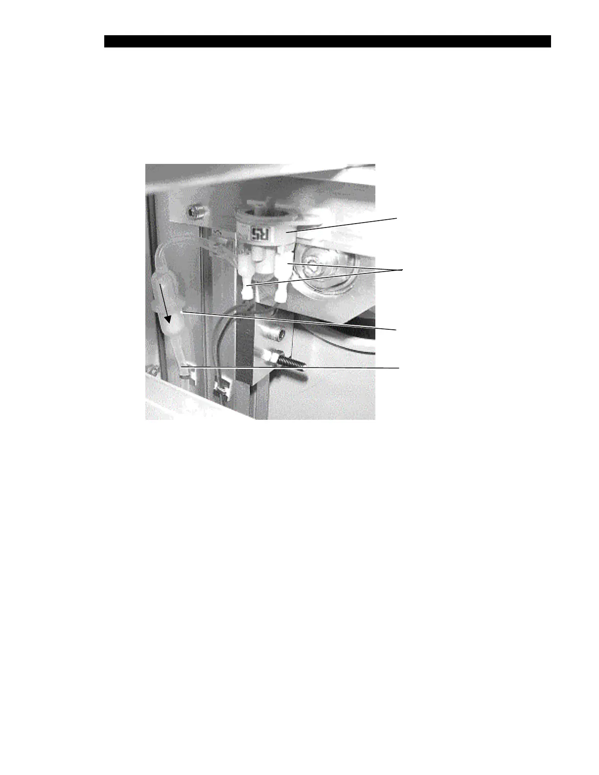
13.3.5 Replacing the Vacuum Switch
The vacuum switch (Part No. 564400200) is connected to the left side of the unit as shown in
Figure 13-7. To remove the vacuum switch, disconnect the Silicon tubing from port A on the
vacuum switch, disconnect the wires, and remove the switch.
Vacuum
Switch
Wires
Vacuum
Filter
Tubing
From Front
Extrusion
Direction
of Flow
Figure 13-7 Vacuum Switch Parts
To Install a New Vacuum Switch:
1 Attach the silicon tubing (Part No. 816400700) to port “A” on the vacuum switch.
2 Attach the Vacuum Filter (Part No. 43000340) between the other end of the
100mm tubing and the free end of the tubing from the front extrusion. Ensure that
direction of the arrow on the vacuum filter is away from the vacuum switch as
shown.
Note: The vacuum switch must be calibrated after it is installed.
During calibration, the waste bottle must be empty and the washer module must
be present with a wash head in the DSX.