Servicing Internal Components
15-10 DSX™ System Service Manual
15.4.4 Replacing the Main Circuit Board
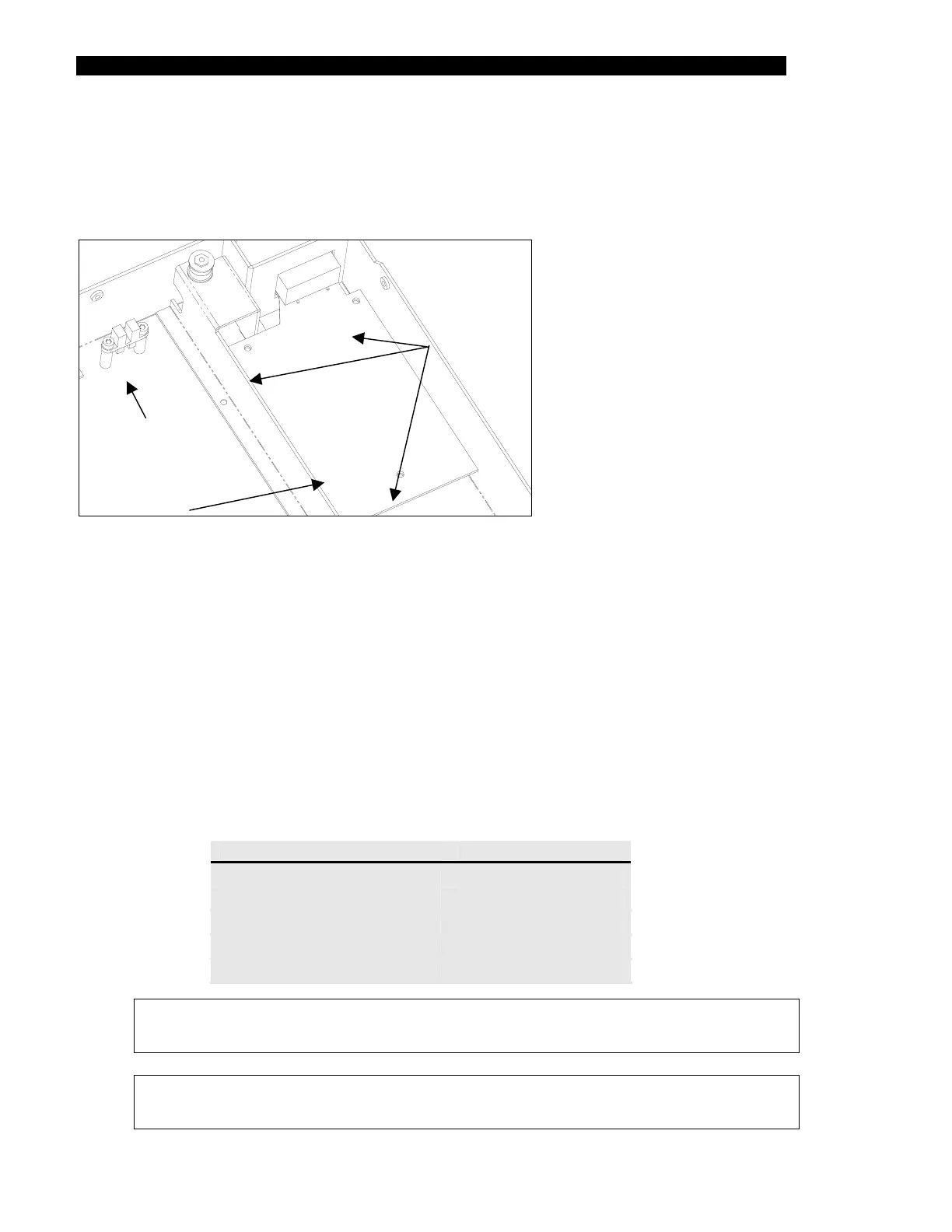
The Ambient Drawer Main Assembly PCB (Part No. 14000570) is located in the right rear
corner of the drawer (Figure 15-9).
Mounting
Screws
Main Circuit
Board
Home Position
Sensor
Figure 15-9 Ambient Drawer Main Assembly PCB
To Replace the Ambient Drawer Main Assembly PCB:
1 Remove the three M3 x 6mm screws and three M3 Nylon washers.
2 Remove all connectors (motor, temperature sensor, front sensor, middle sensor
and rear sensor).
3 When reinstalling a new printed circuit board, remove the temperature sensor
section by snapping it off (refer to Replacing the Temperature Sensor on
page 15-12). In addition, note that the eject plug on the printed circuit board
should be left empty.
4 Reattach the cables to the PCB connectors as shown below:
Cables PCB Connector
Temperature Sensor
J10
Front Sensor
J2
Mid Sensor
J3
Home Sensor
J4
Motor
J6
Note: When replacing the main circuit board, ensure that the board does not
contact the side of the lower enclosure.
Note: After installing a new main circuit board, the module must be calibrated
using DynexTest software.