Servicing Internal Components
DSX™ System Service Manual 15-11
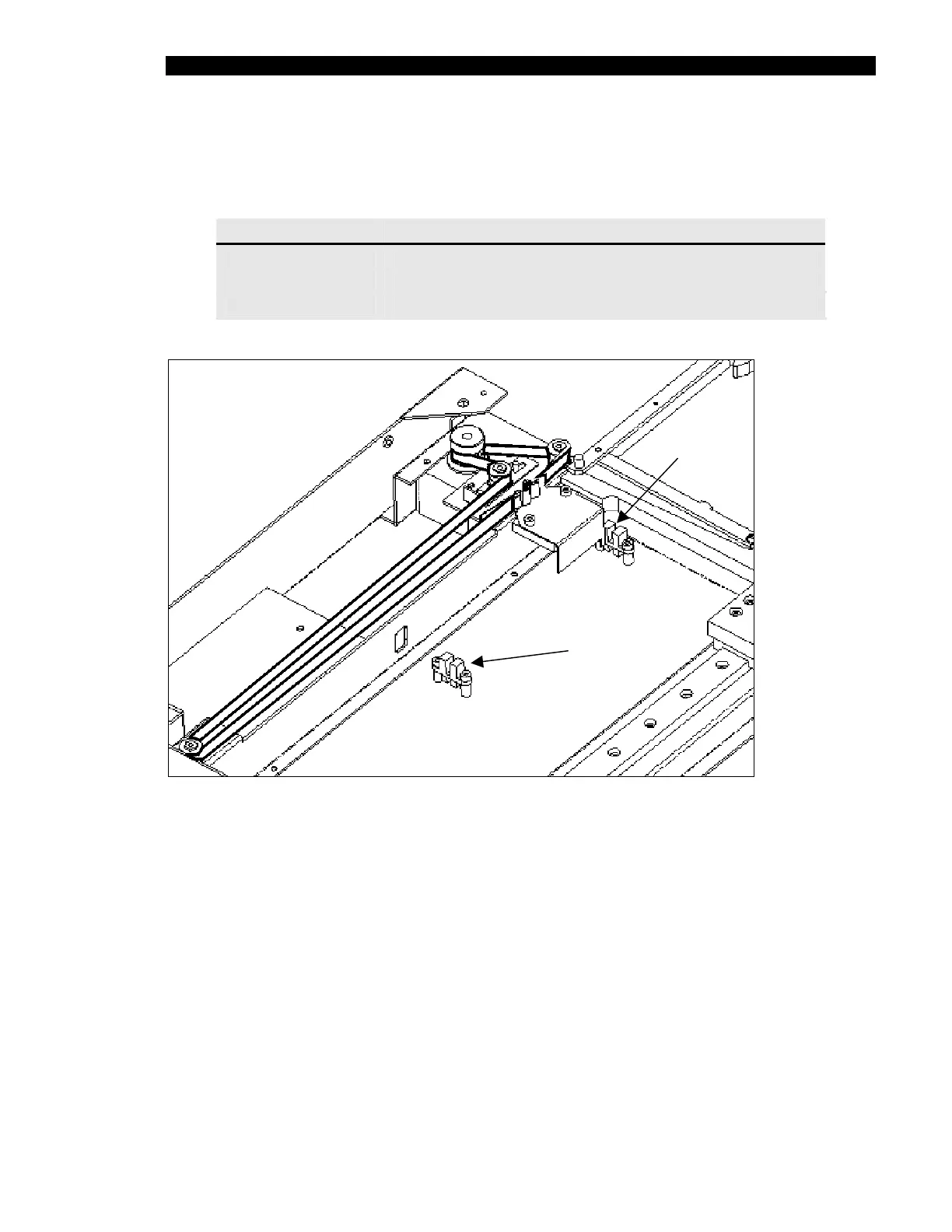
15.4.5 Replacing the Optical Sensors
Three optical sensors are mounted in the lower enclosure:
Sensor Location
Front Sensor Closest to the motor (see Figure 15-10)
Mid Sensor Center of drawer travel distance (see Figure 15-10)
Home Sensor
Rear of lower enclosure (see Figure 15-9)
Front Position
Mid Position
Figure 15-10 Location of Front and Mid Optical Position Sensors
To Replace a Position Sensor:
1 Unfasten the sensor by removing the two socket head screws and lock washers.
2 Disconnect the sensor cable from the ambient drawer main circuit board. Remove
the cable through the access hole, noting the position of the access hole. Note
where the cable is secured with a tie wrap.
3 Secure the new sensor into position, using the two socket head screws and lock
washers.
4 Route the connector through the access hole noted in Step 2. Replace any tie
wraps.
5 Plug the connector into the PCB connector (see Step 4 on page 15-10).