Repairing/Replacing Internal Components
DSX™ System Service Manual 11-33
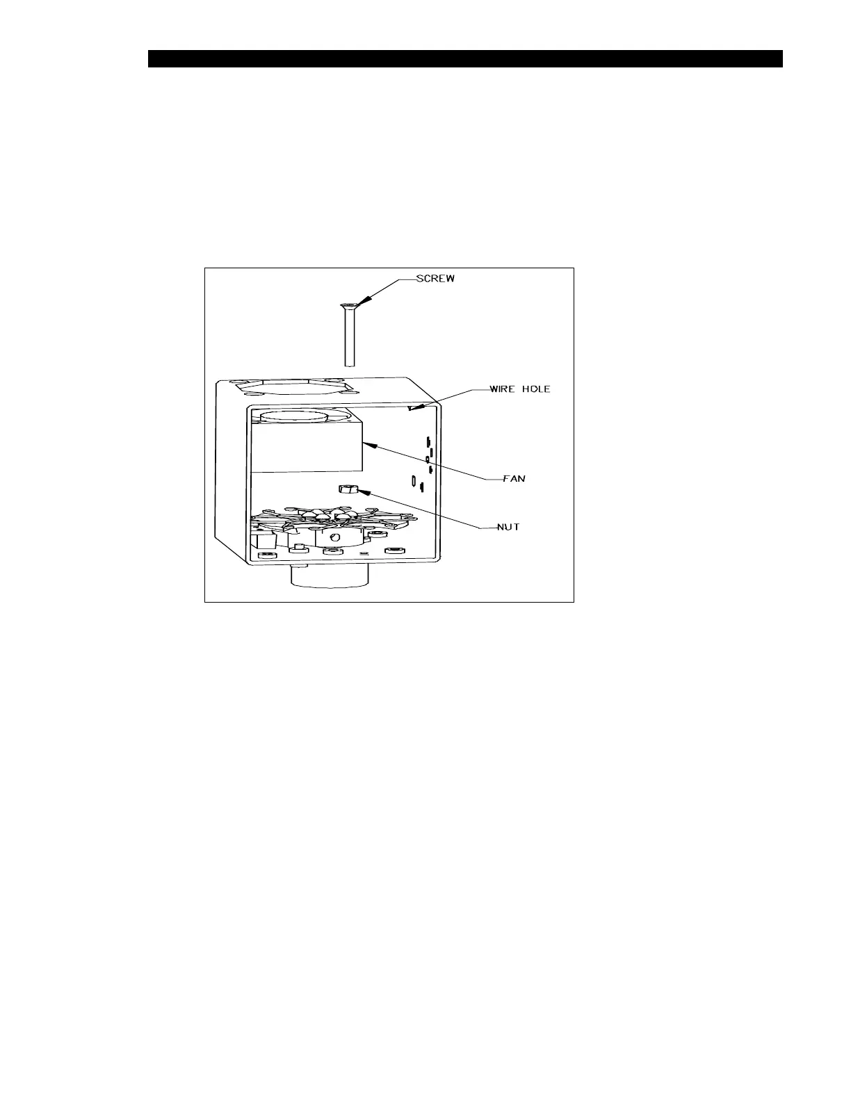
11.4.14 Removal/Replacement of the Optics Cube Fan
To Remove the Optics Cube Fan:
1 Remove the fan from the optics cube by removing the 4 M3 x 25mm flat head
screws that secure it to the cube (Figure 11-28).
Figure 11-28 Optics Cube Fan
2 Carefully cut away the RTV around the fan wires and remove the connector from
the wires.
3 Pull the fan out of the cube.
To Reassemble the Optics Cube Fan:
1 Mount the fan in the optics cube using the four M3 x 25mm flat head screws and
Loctite 242.
2 Install the fan to blow into the cube with the wire going out the access hole on the
right. Attach the 2mm 2-pin connector to fan wires using 2 contact crimps. Pin 1
connects to the Black wire and Pin 2 connects to the red wire. The connector has
a small notch that indicates the position of Pin 1. The wires should be twisted 1
turn per inch before termination. The final length of the terminated wires should
be 5.25 inches.