The Drive Assemblies
12-2 DSX™ System Service Manual
12.3 The Drive Assemblies
Note: For the sake of brevity, only the X-Drive assembly is described in this
section. The general mode of operation of the Y-Drive and Z-Drive assemblies is
similar to that of the X-Drive, but the position and configuration is different. For
additional information, see Chapter 13.
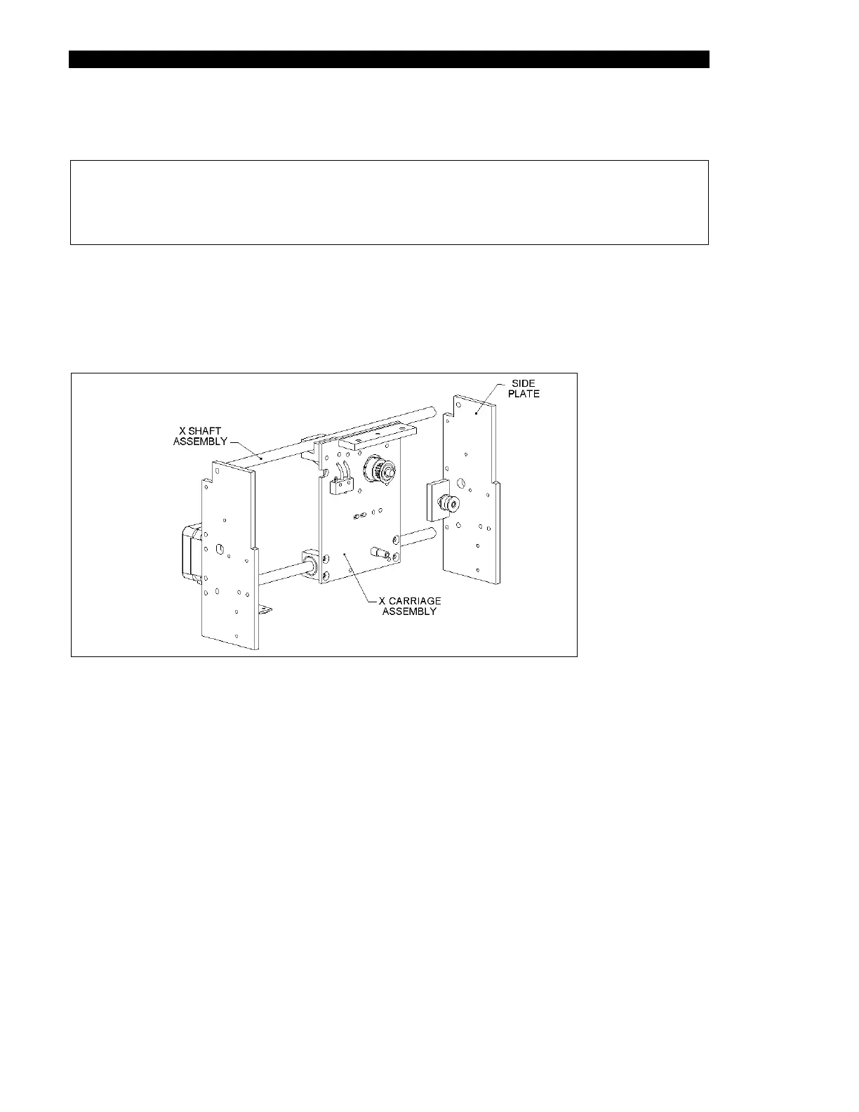
The X-Drive Assembly, shown in Figure 12-1 through Figure 12-3, includes a stepper motor
that is mounted on a carriage that travels along the X-Shaft Assembly between the two side
plates of the Drive Assembly. The X-Drive timing belt is used to drive the assembly and is
installed between the X-Drive Motor and an idler bearing (Figure 12-3).
Figure 12-1 X-Drive Assembly