The X-Drive and Y-Drive
DSX™ System Service Manual 6-3
6.2 The X-Drive and Y-Drive
6.2.1 General Design of the Drive Mechanisms
The XY module controls the movement of the pipette arm in the X- and Y- directions. The
pipette tip can be driven in either direction on an independent basis or can be driven in both
directions simultaneously.
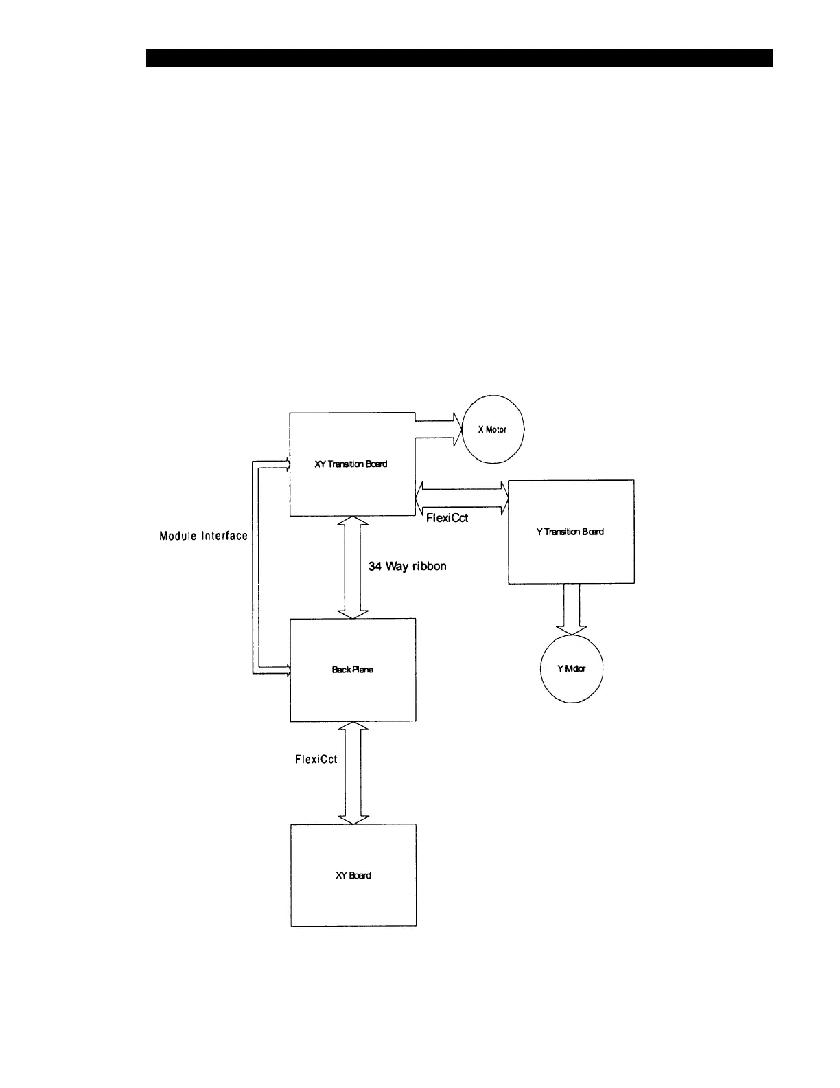
The X and Y-Drive mechanisms each include a stepper motor under the control of a transition
board (printed circuit board) as shown in Figure 6-1 through Figure 6-4. The stepper motor
drives a belt that moves the pipette module in the specified direction. An encoder/counter is
associated with each motor to ensure correct positioning and an optical sensor is mounted on
the rail as a reference.
Figure 6-1 Circuit Board Diagram – Board Breakdown