Repairing/Replacing Internal Components
11-22 DSX™ System Service Manual
5 Wrap the new belt around the middle idler, the rear idler and the front idler, then
loop it around the motor assembly.
6 Loosely fasten the motor to the chassis using 4 M3 x 6mm socket head cap
screws, M3 flat washers and M3 lock washers.
7 Route the wire from the motor to the right in the back. Apply 7 in-lbs of torque to
tighten the screws.
Note: When tightening the screws, use torque driver SN160 to tighten the
screws to 7 in-lbs.
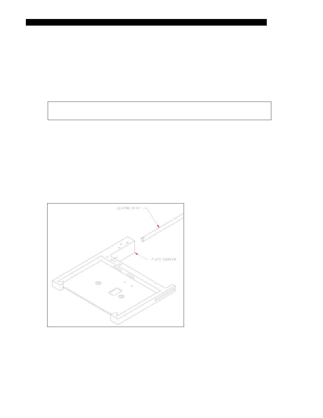
11.4.4 Removal/Replacement of the Plate Carrier Assembly
1 Remove the assembly by unscrewing the two support blocks and two M2.5 x
12mm Flathead screws from the bottom of the module chassis.
2 Lift and remove the Plate Carrier from the module chassis.
3 Remove the plate carrier from the bearing shaft as shown in Figure 11-16.
Figure 11-16 Plate Carrier Assembly