Post-Service Checkout Protocol
3-12 DSX™ System Service Manual
3.5.6 Manual Adjustment of the Module Calibration
Manual adjustment of a module may be required using a standard plate carrier if the unit
does not put and get the plates properly. Prior to starting this, the user should put a
standard carrier into the module that requires a manual adjustment.
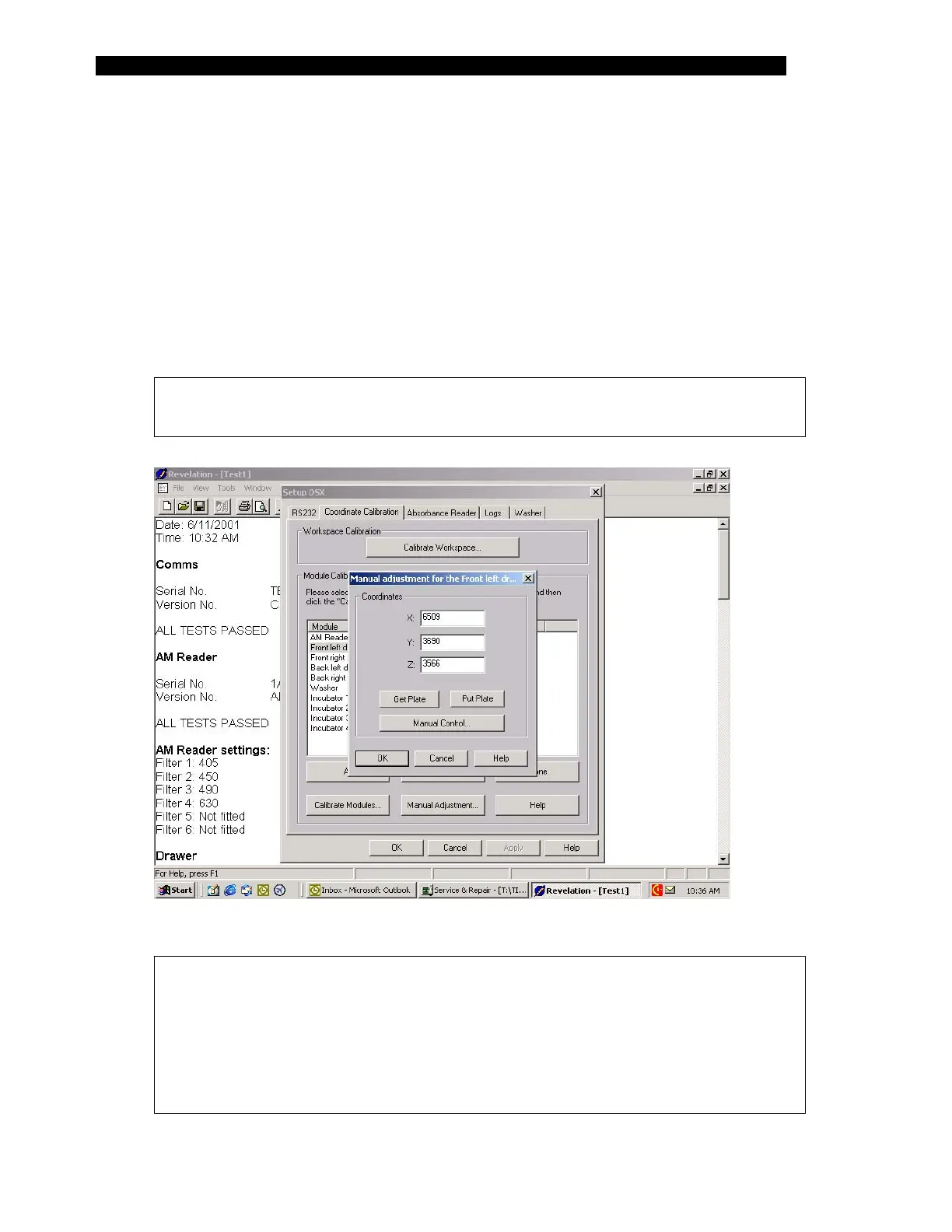
1 Start Revelation, select Tools and then select Configure System. Select the
Coordinate Calibration tab of the Set-up DSX dialog box (Figure 3-2).
2 Select the module to manually adjust by left clicking on it with the mouse and
then select Manual Adjustment.
Note: The front left drawer is used as an example. The other modules are
adjusted in the same manner.
Figure 3-5 Front Left Drawer Manual Adjustment Dialog Box.
Note: The values in the Manual Adjustment Dialog Box for the three axes
represent approximately 0.01mm in travel. For example, the value reported
in Figure 3-5 for Z is equivalent to the step count (3566) multiplied by.0625
would provide the distance in millimeters from the Z home position. The
Y & Z step count multiplication factor is .0625 and the X is .0600. The home
position for the X is the farthest left position or 0, the Y is farthest inward
position or zero and the Z is the up most position or zero.