Repairing/Replacing Internal Components
11-18 DSX™ System Service Manual
To Remove the Main Board:
1 Disconnect the connectors from the board and unfasten the Main Board by
removing the 6 M3 x 8mm socket head cap screws and 6 M3 lock washers.
2 Lift the board off of the standoffs.
=
CAUTION: SINCE THE PHOTODIODES ARE EXPOSED DURING
THIS OPERATION, CARE SHOULD BE EXERCISED WHEN
HANDLING OR STORING THE BOARDS TO ENSURE THAT THEY
ARE NOT DAMAGED.
To Install the Main Board:
1 Installation is the reverse of the removal.
2 After installation, test and calibrate the module using DynexTest software.
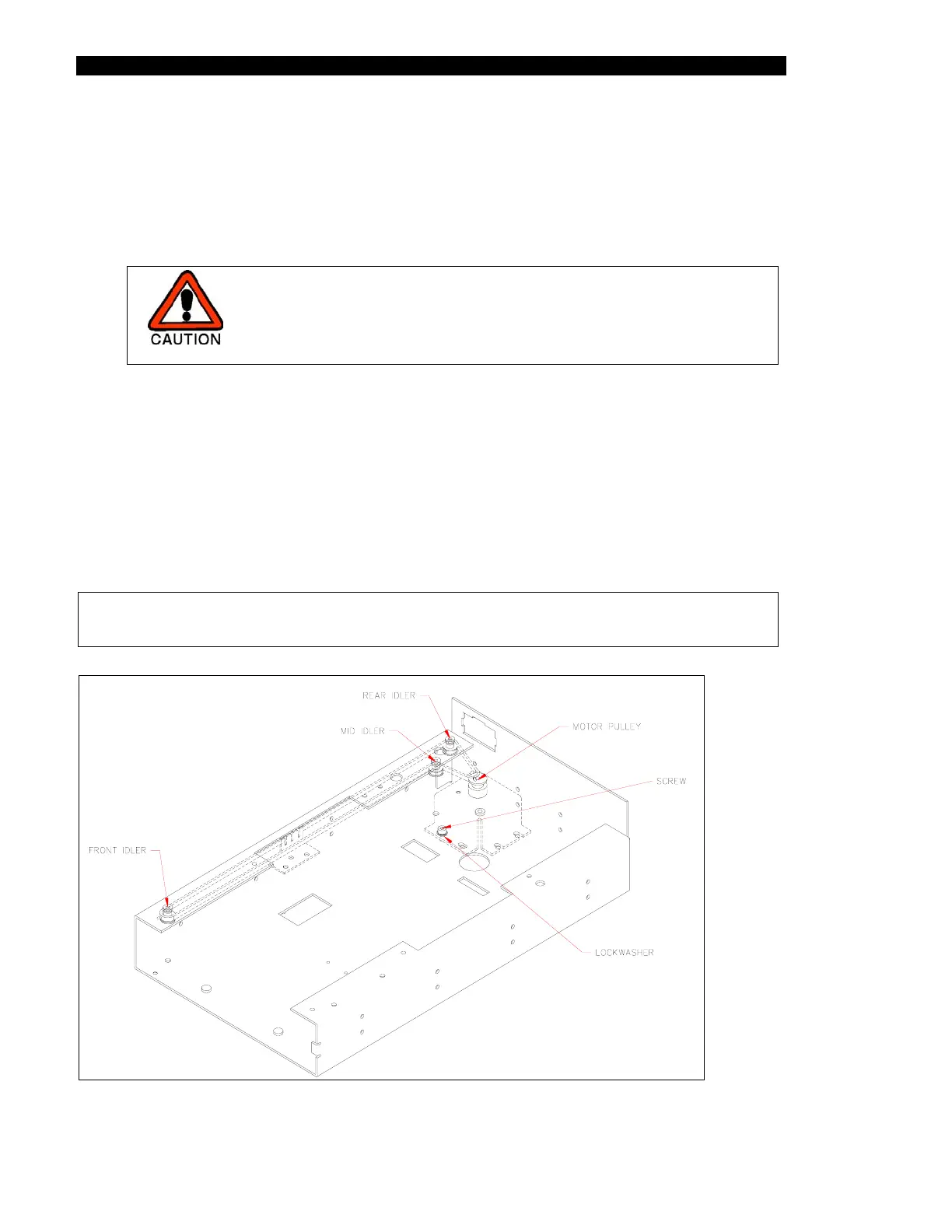
11.4.2 Removal/Replacement of the Plate Carrier Motor
The plate carrier motor drives the carrier belt that draws the plate into the module, positions
each row for measurement and holds the plate in position (Figure 11-11).
Note: If the plate carrier, plate carrier motor or the drive belt is removed or
replaced, use the alignment plate before running samples again.
Figure 11-11 Plate Carrier Drive