Cabling
17-18 DSX™ System Service Manual
17.4 Cabling
The back plane includes a series of cables and the back plane board that connect the EPOD to
the various modules in the DSX system.
Note: The grooved side of all cables must face down or left. When a cable is
installed, make certain to tie it down to the position it was removed from as it
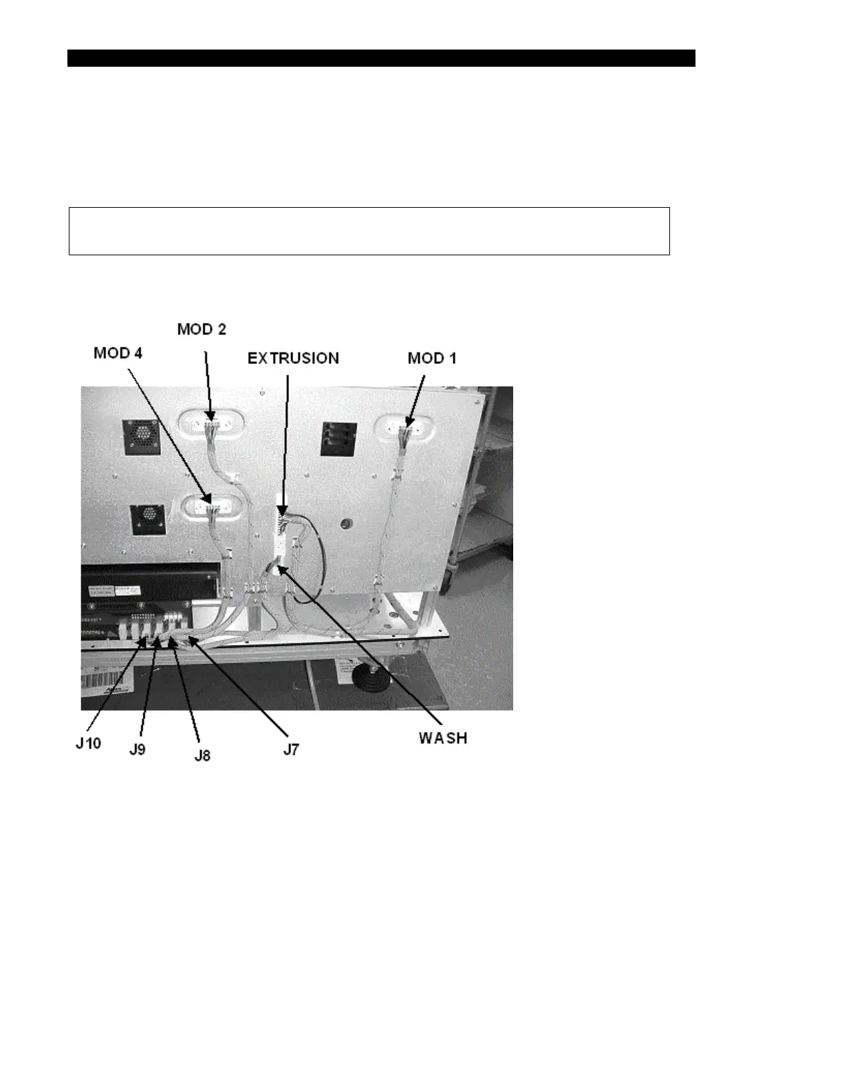
The location of these cables is presented in Figure 17-16 and Figure 17-17.
Figure 17-16 Back Panel Cabling - Panel 1
Cable (Part No. 15001070) is connected from MOD 1 to J7 of back plane board •
•
•
•
•
•
Cable (Part No. 15001050) is connected from WASH to J8 of back plane board
Cable (Part No. 15001060) is connected from MOD 2 to J9 of back plane board
Cable (Part No. 15001050) is connected from MOD 4 to J10 of back plane board
The front cover extrusion harness is connected into the EXTRUSION slot.
Connect black and red wires from extrusion harness to pump wires.