166
20. Color Correction
The switcher has two color correction filters for each M/E. They can be assigned to inputs, M/E
outputs and keys. In addition, Clip adjustment allows users to set signal level limits for all color
correction outputs. The following features are available:
2 color correction filters available
Separate or group adjustment for RGB White/Black/Gamma levels.
Three Color Correction modes available: BAL(balanced), DIF(differential) and SEPIA.
Two Clip modes available: Y/C and RGB(GBR)
Color Correction and Clip settings can be saved to events.
20-1. Color Correction
20-1-1. Assigning a Bus or Signal to a Color Corrector
(1) Press MENU in the CONTROL block, then SETUP to display the [SETUP] top menu.
(2) Turn F1 to select INPUT, then press F1 to display the [SETUP - INPUT] menu.
(3) Turn F1 to select CC, then press F1 to display the [SETUP - INPUT - CC] menu.
(4) Turn F1 to select a color corrector. Channel 1 of M/E1 (M1Ch1) is selected in the menu
example below.
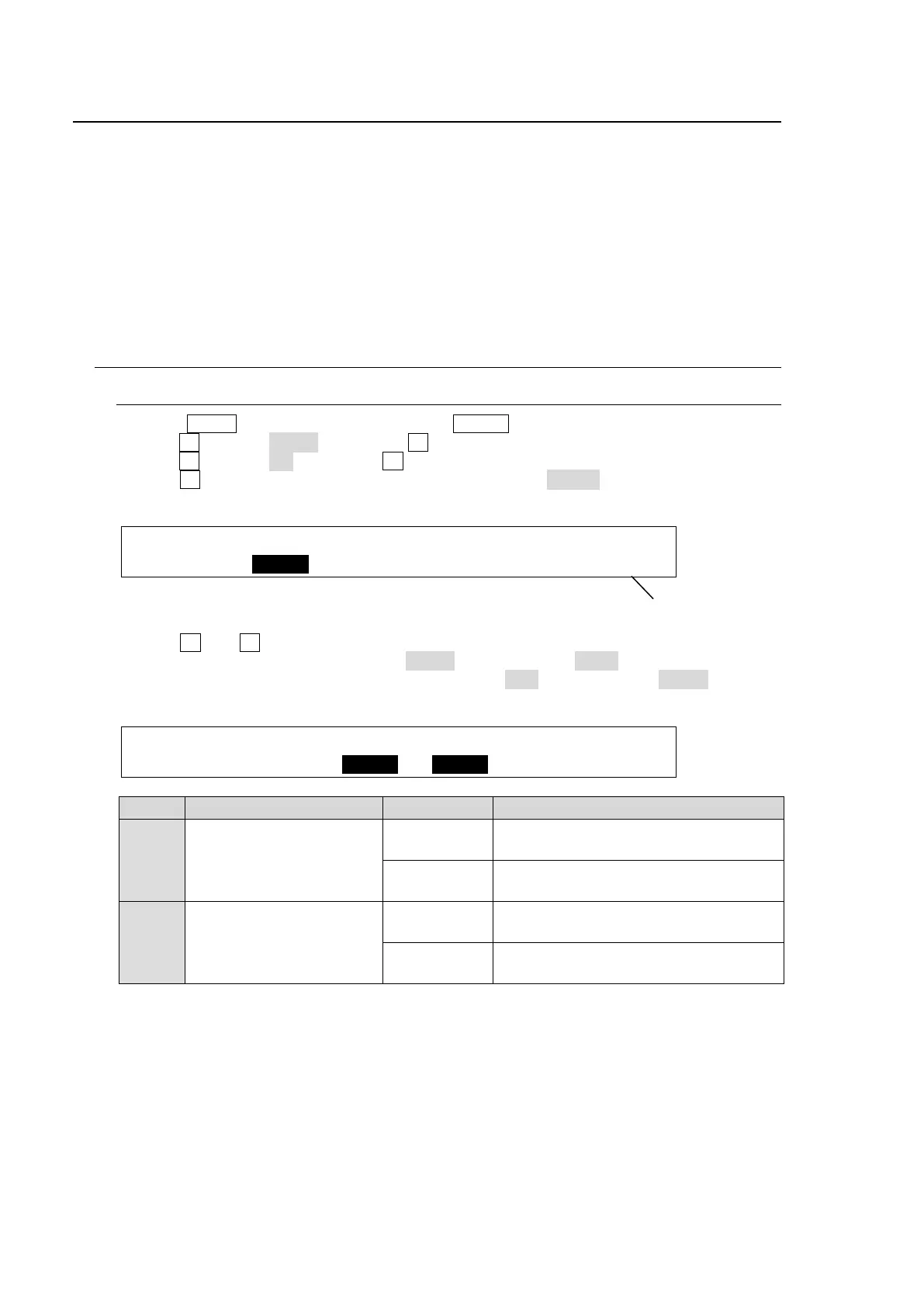
INPUT :SELECT : TYPE :SIGNAL :ENABLE : 1/6
CC TOP : =M1Ch1: =INPUT: =IN01 : =OFF : M1-1
(5) Turn F2 and F3 respectively to select a signal to be corrected. For example, to assign
STILL 1 to the channel, set TYPE to INPUT and SIGNAL to STIL1. To assign A BUS, an
M/E combined signal, to the channel, set TYPE to BUS and SIGNAL to A BUS. (See the
tables below.)
INPUT :SELECT : TYPE :SIGNAL :ENABLE : 1/6
CC TOP : =M1Ch1: =INPUT: =STIL1: =OFF : M1-1
M/E SELECT (channel) setting TYPE setting SIGNAL setting
M/E1
M1Ch1
M1Ch2
INPUT
IN01 - 24
STIL1 - 4
BUS
A BUS, B BUS
M1K1F, M1K2F, M1K3F, M1K4F
M/E2
(*1)
M2Ch1
M2Ch2
INPUT
STIL1 - 4
BUS
A BUS, B BUS
M2K1F, M2K2F, M2K3F, M2K4F
If both INPUT and BUS type channels are applied to the same signal, the BUS type channel
settings are used.
(*1) Only available if an optional HVS-39EXTME card is installed.
Selected channel