21
2-4. Interfaces
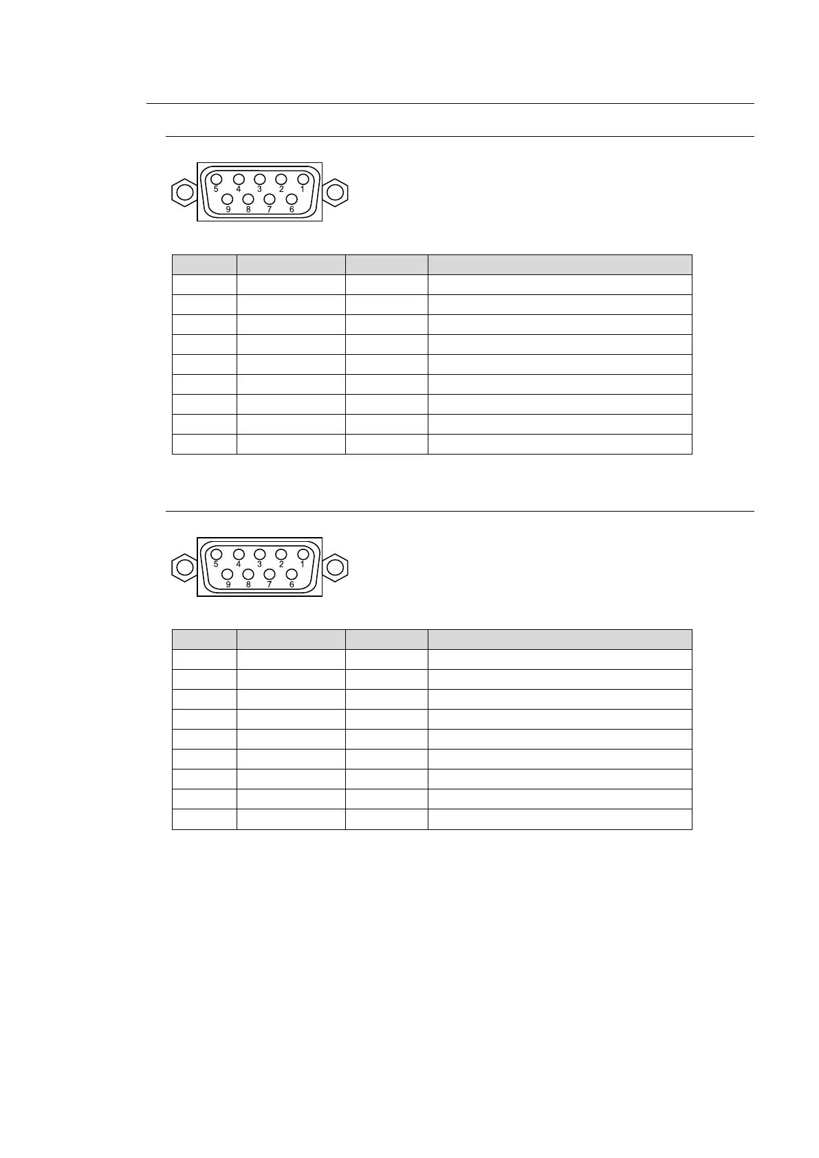
2-4-1. EDITOR Connector
Pin Assignment Table
Pin No. Signal Name In/Out Description
2 T- Out Transmit data (-)
4 SG Signal ground
5 NC Not used
6 SG Signal ground
7 T+ Out Transmit data (+)
8 R- In Receive data (-)
2-4-2. RS-422 Connector 1-6
Pin Assignment Table
Pin No. Signal Name In/Out Description
1 FG Frame ground
2 R- In Receive data (-)
3 T+ Out Transmit data (+)
4 SG Signal ground
5 NC Not used
6 SG Signal ground
7 R+ In Receive data (+)
8 T- Out Transmit data (-)
9 FG Frame ground
RS-422 ports are used for the following device connections. See the related chapters to
configure the connections.
HVS-30RU: See section 33-1. "Connecting Remote Panels (HVS-30RU)."
Tally Units: See section 24-2. "Tally Output."
VTR/VDCP devices: See section 25. "VTR / VDCP Control."
Routers: See sections 26 and 27.
with inch screws
with inch screws

 Loading...


