197
25. VTR / VDCP Control
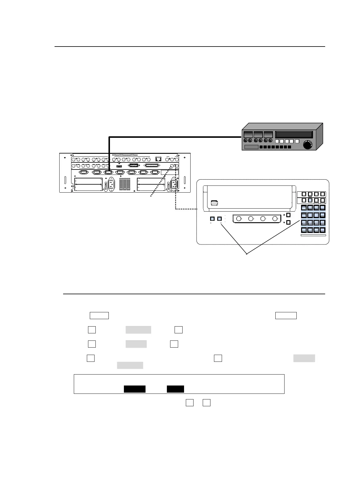
The switcher can control video tape or video disk recorders via RS-422 using the VTR or VDCP
protocol. Up to 4 channels are available. Connect a device to a desired RS-422 port, configure the
port and select a channel for VTR or VDCP following the procedures in this chapter.
System Configuration Example
1) Connect HVS-390HS to a VTR using an RS-422 port and configure the port. (See section 25-1.)
2) Assign a VTR channel to the RS-422 port. (See section 25-2.)
3) Control the VTR using the VTR/VDCP menu (see section 25-4) or using USER buttons (see
section 25-5).
25-1. Assigning a VTR or VDCP Channel to an RS-422 Port
At first assign a VTR or VDCP channel to an RS-422 port as shown below.
(1) Press MENU in the CONTROL block above the KEYPAD, and then press SETUP to display
the [SETUP] top menu.
(2) Turn F1 to select SYSTEM. Press F1 or the page down button to go to the [SETUP -
SYSTEM] menu.
(3) Turn F1 to select RS-422. Press F1 or the page down button to display the [SETUP -
SYSTEM - RS-422] menu.
(4) Turn F1 to select a desired RS-422 port. Then turn F2 to select a VTR channel (VTR1-4) or
VDCP channel (VDCP1-4).
SYSTEM :SELECT :FUNC :BAUD :PARITY : 1/1
RS-422 : =PORT1 : =VTR1: =38400: =ODD :
(5) Change BAUDRATE and PARITY using F3 or F4, if needed.
USB M EMORY
ALARM
POWER1
POWER2
USER BUTTON
1 2
F1
F2 F3
F4
PA GE
SELEC T / KE YPAD
5
2
REC AL L
PASTE
4
1
6
3
DEC
SEQUENCEEVENTWIPE MA CRO
CON TR OL
MEMORY
ME NU USER B UT TON COPY/SWAP SEQ EDIT
987
AT TAC H
INC
ME NU
COP Y
ST ILL MA TT
SWAP NEW
FILE
I NS
KEY4KEY3KEY2KEY1
DETTACH
A DDDELCUTPLAY
+/-
CLEAR
WIPE
STO P
0
COP Y
STORE
ENTER
O VWR
ED IT OR
OPT I ON SL OT
AC100-240V 50/60Hz IN
2
RS-422
AUX HDMI GPI INSDI OUTPUT
1 2
A
B
1 2 1 2 1 2
1 2 3 4 5 6 7 8
SDI INPUT
9 10 11 12 13 14 1615
GPI/TALLY OUT
OPT I ON SL OT
C
D
1
AC100-240V 50/60Hz IN
RATING LABEL
T O OU
GEN LOCK
REF IN REF OUT
L AN
1 2 3 4 5 6
the VTR/VDCP menu.
Controlling VTR using user buttons.
Ω



 To Next Page