195
24-2-3. Tally Output Settings (HVS-30TALR)
Up to two cards of HVS-30TALR (Tally Output Expansion Card) can be installed to the
HVS-390HS. Each card has 18 channels, therefore up to 36 channels (two cards) available
for tally output. See section 2-4-6 "TALLY OUT Connector (HVS-30TALR)" for the default pin
assignments of the connector.
Selecting Tally Color for an Output Bus
See section 24-2-1 "Tally Color Setting." The Tally Color settings made in this menu are
shared with those for the GPI/TALLY OUT connectors, TALLY OUT connector (HVS-30TALR)
and Tally Units.
Setting Pin Assignments for TALLY OUT connector
(1) Press the page up or down button to return to the [SETUP - GPI/TLY] menu.
(2) Open the [SETUP - GPI/TLY - 30TALR] menu.
SETUP :>TLY COL >GPI IN >GPI OUT>OU GPI/O
GPI/TLY :>TALLY1 >TALLY2 >TALLY3 >30TALR
GPI/TLY :ENABLE :P NO : FUNCTION : 1/1
30TALR : =ON : =1-1: =Out:RED TALLY-IN01
(3) Turn F2 to select a channel under P NO.
Channels are specified as follows: [Card number]-[Channel number]. For example, "1-10"
represents the 10th channel of Card 1. See "Card Number of HVS-30TALR" below.
(4) Turn F3 to select a tally to be assigned under FUNCTION. See the table "GPI
OUT/TALLY function." (p.190)
(5) Set Enable to ON to enable all tally outputs of the TALLY OUT connector.
The HVS-
30TALR cards can send GPI outputs. To output GPI signals, select the
desired GPI function under FUNCTION. See section 24-1-2 "GPI OUT" for details.
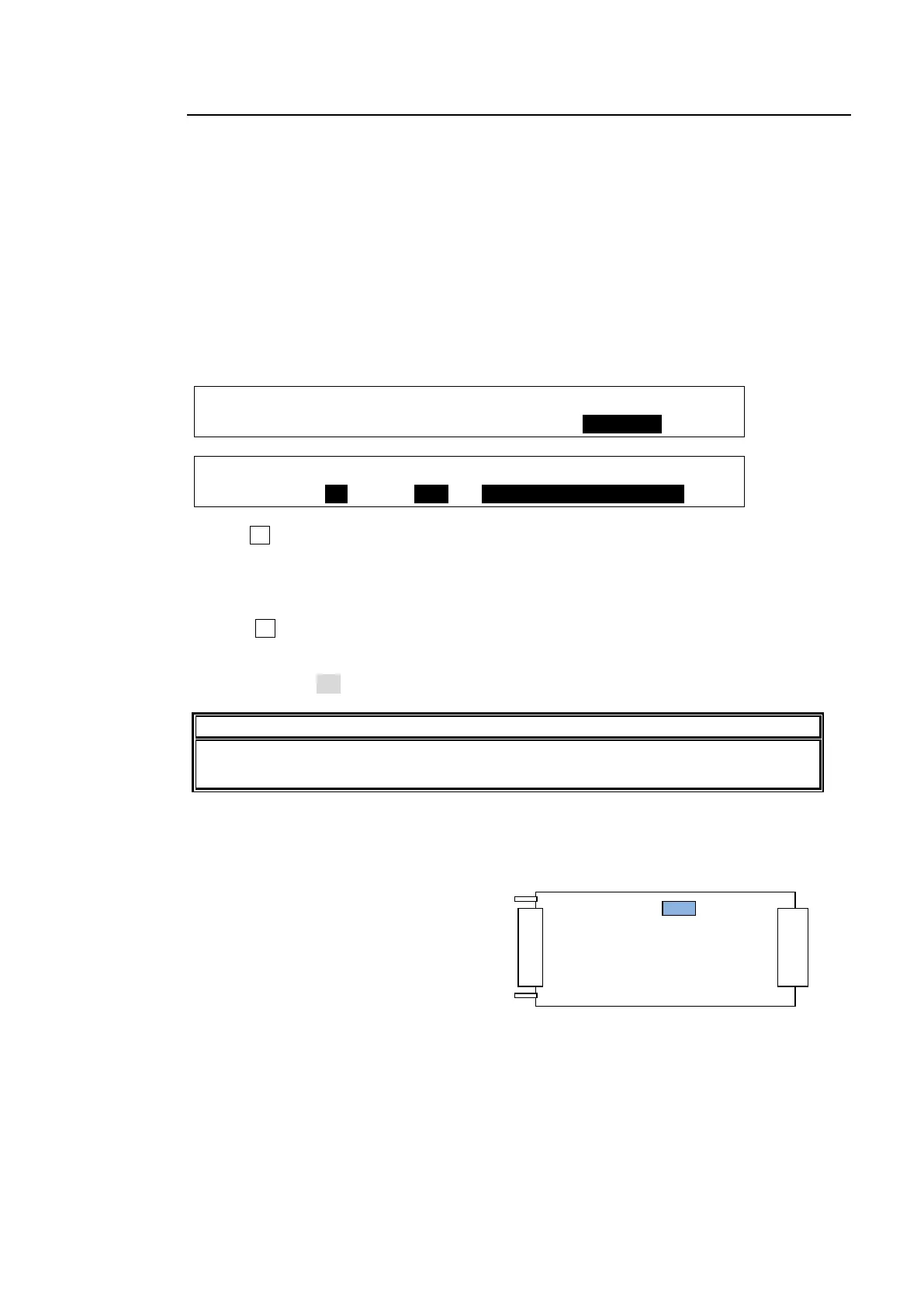
Card Number of HVS-30TALR
The card number, Card 1 or Card 2, is chosen by the internal dip switch (DS 1) on the
HVS-30TALR card.
If set to Card1:
DS1-1: ON
DS1-2: OFF
If set to Card2:
DS1-1: OFF
DS1-2: ON
* DS1-3 to DS1-8 are all set to OFF, do not change the settings.

 Loading...


