K117sm4e3
4-27
2. Make a Test Print making reference to [8. 9 Test Print Mode].
As the Negative Developer Bias is supplied to the Developer Roller during the Test Print, check
the voltage with the multi-meter.
The standard value of the Negative Developer Bias for each type of media is:
Plain paper -230 +/-5V against the ground
Tracing paper -230 +/-5V against the ground
Film -230 +/-5V against the ground
If the above values are not satisfied, go to the next step.
3. If the value (voltage) is -180 +/- 5V
, Developer Bias may be automatically adjusted by Density
Compensation Process. (normal operation in such a case)
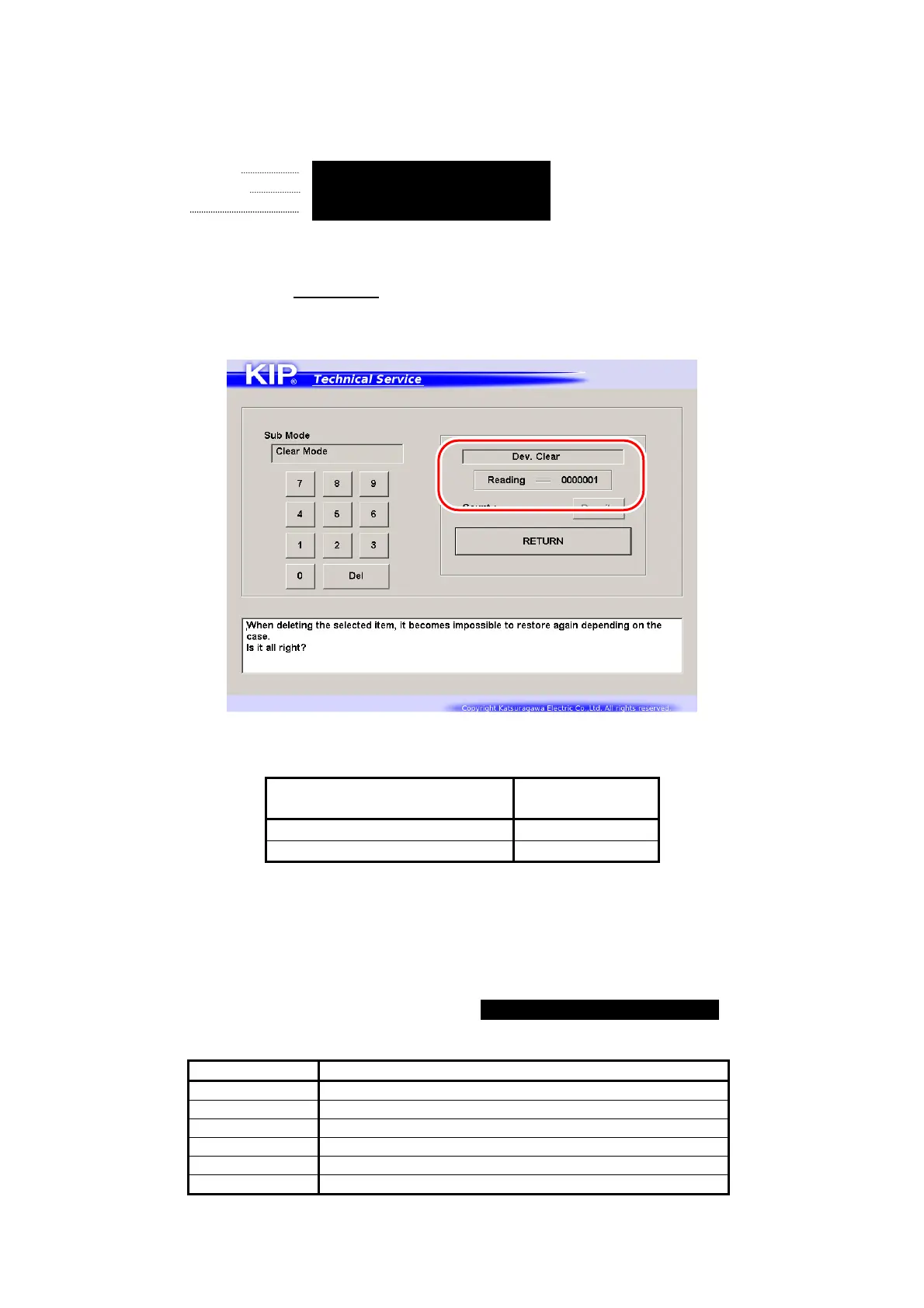
Enter Special Operation Mode and then
“0006 Dev. Clear”.
The voltage “-180V +/- 5V” is correct when the above 7-digit value shows
“0000000”.
7 digits (current Auto
Adjustment Level)
Supposed
Developer Bias
0000000 -180 +/-5V
0000001 / 0000002 / 0000003 -230 +/-5V
Refer to [8.11.3 Reset of Bias Adjustment by Density Compensation Process] for checking the
current Auto Adjustment Level.
If not satisfied, go to the next step for manual Developer Bias adjustment.
4. Select the Adjustment Mode, select each of following Sub Mode Numbers, and change the
setting value so that the output voltage satisfies -230 +/-5V against the ground.
Refer to [8.6.3 022 to 027 Developer Bias] for the detail.
Sub Mode No. Contents
022 Developer Bias (Plain paper)
023 Developer Bias (Tracing paper)
024 Developer Bias (Film)
025 Developer Bias (Plain paper : Special)
026 Developer Bias (Tracing paper : Special)
027 Developer Bias (Film : Special)