K117sm3e1
3-9
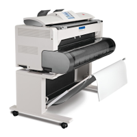
3. 1. 2. 4 Development
The Developer Roller, which is evenly covered with the toner, is contacted to the Drum because
the Developer Unit is pressed to the Drum. (The width of contact point is about 5mm.)
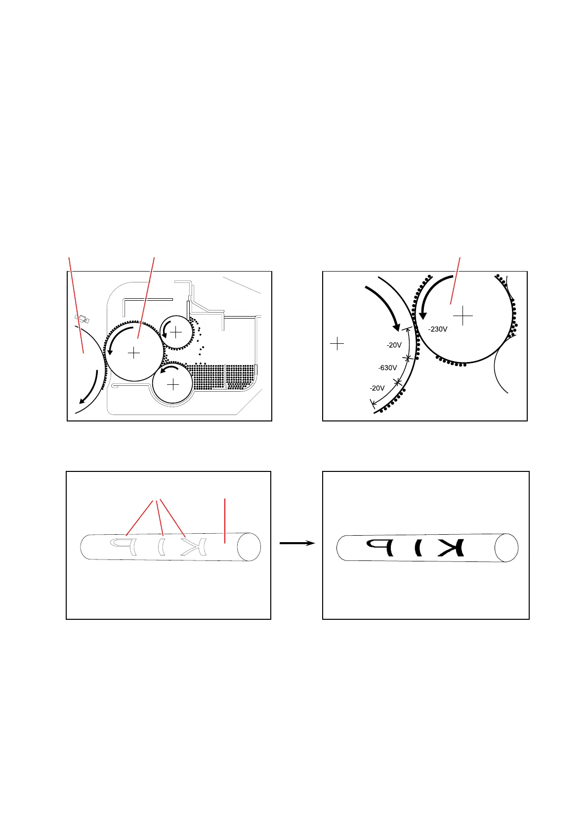
The Developer Roller is supplied with -230V during the print cycle.
And both -630V area and -20V area exist on the Drum because the Electrostatic Latent Image has
been formed in the former Exposure process.
Seen from the voltage of Developer Roller Bias (-230V), the -20V area on the Drum is relatively
“positive”. So the toner moves from the Developer Roller to the -20V area of Drum.
On the other hand, the -630V area is relatively “negative” seen from the Developer Roller.
So the toner does not move to the -630V area but stays on the Developer Roller.
A visible toner image is formed on the Drum as a result.
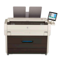
Drum Developer Roller Developer Roller
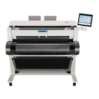
Before Development After Development : Toner moves
only to -20V area.
(Invisible Electrostatic Latent Image) (Visible toner image)
-20V -630V
Drum