K117sm4e2
4-2
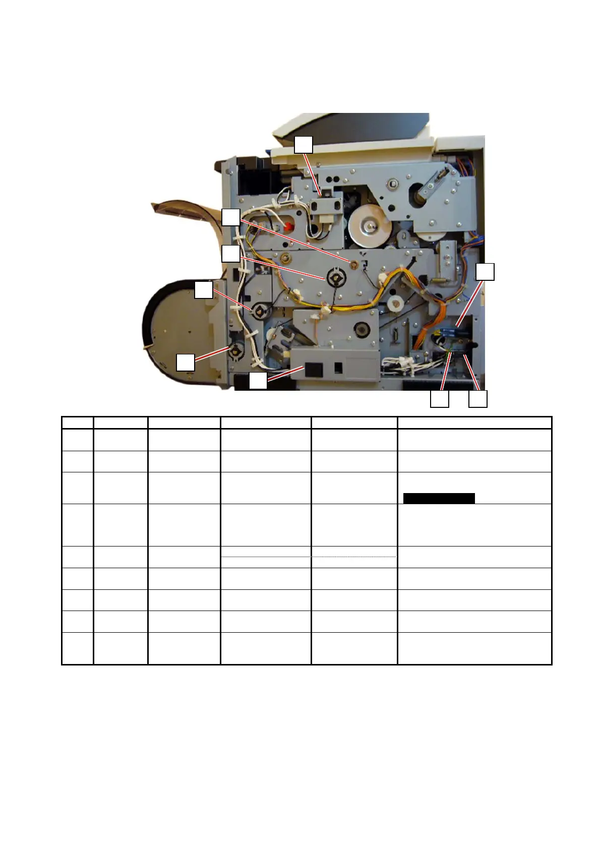
4. 2 Electrical Component Location
4. 2. 1 Right
Item Symbol Signal name Name Type Function
1 SW1 - Switch
(Power Switch)
AJ8R2004BBCF Switches ON/OFF the machine
2 MS1 - Switch
(Upper Unit Switch)
FA1L-CA22 Shuts off the AC power to the
DCP1 when the Upper Unit is open
4 LF1 - Noise Filter Removes the noise from the AC
line
120V model only
5 CB1 - Breaker X28-XQ1A-15
(for 120V model)
X28-XQ1A-10
(for 230V model)
Protects the AC line from the over-
current
6 INLET - Noise Filter Assy 120V model Inputs the AC Power from a wall
Inlet Assy 230V model outlet
7 CL3 R1FD_CL Clutch
(Roll Feed Clutch)
MCA-30A Picks up the roll media’s leading
edge to wait position
8 CL2 FEED_CL Clutch
(Feed Clutch)
MCA-30A Feeds the roll media
9 CL1 REGIST_CL Clutch (Registration
Clutch)
MCA-30A Meets the image head and the
leading edge of media
10 CL4 GUIDE_CL Clutch
(Guide Clutch)
DSTC-40G Pushes up the guide plate (just
after Tr/Sp) to control the LE
approach to Fuser Entrance Plate.
2
1
4 5
6
7
8
9
10