K117sm7e2
7-17
7. 2 Troubleshooting - Image Quality
7. 2. 1 Basic Image Adjustment
The followings are the settings specified to the image creation components.
When a defective image is printed out, please check whether or not these settings are satisfied for
the beginning.
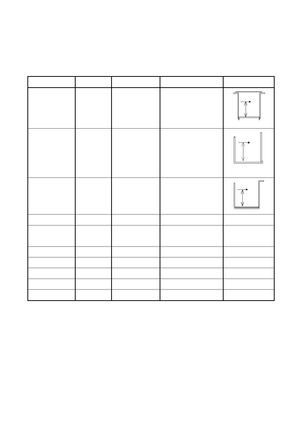
Component Check Point
(PW11720)
Designated voltage Way of adjustment Corona Wire Height
Image Corona CP11 (+)
CPCOM (-)
1.3 +/-0.05VDC VR101
Transfer Corona CP21 (+)
CP22 (-)
1.0 +/-0.05VDC Adjustment Mode
No.029 (Plain)
No.030 (Tracing)
No.031 (Film)
Separation Corona
(AC)
CP31 (+)
CPCOM (-)
5.0 +/-0.05V VR302
Separation Corona
(DC)
CP33 (+)
Ground (-)
-250 +/-5VDC VR303
Negative Developer
Roller Bias
OUTPUT2 (+)
Ground (-)
-230 +/-5VDC Adjustment Mode
No.022 (Plain)
No.023 (Tracing)
No.024 (Film)
Positive Developer
Roller Bias
CP41 (+)
CP42 (-)
0.350 +/-0.005V VR401
Toner Supply Roller
Bias
OUTPUT1 (+)
OUTPUT2 (-)
the same voltage as
Developer Bias
-
Regulation Roller
Bias
OUTPUT2 (+)
OUTPUT3 (-)
-80 +/-5VDC Adjustment Mode
No.622
Positive Cleaning
Roller Bias
OUTPUT5 (+)
Ground (-)
+450 +/-5VDC VR001
Negative Cleaning
Roller Bias
OUTPUT5 (+)
Ground (-)
-550 +/-5VDC VR002
NOTE: Developer / Regulation Bias may be controlled by Density Compensation Process.
11mm
10.4mm
11 mm