K117sm3e1
3-22
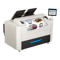
3. 2 Scan Process
3. 2. 1 Data flow in scan and copy (for Old Scanner)
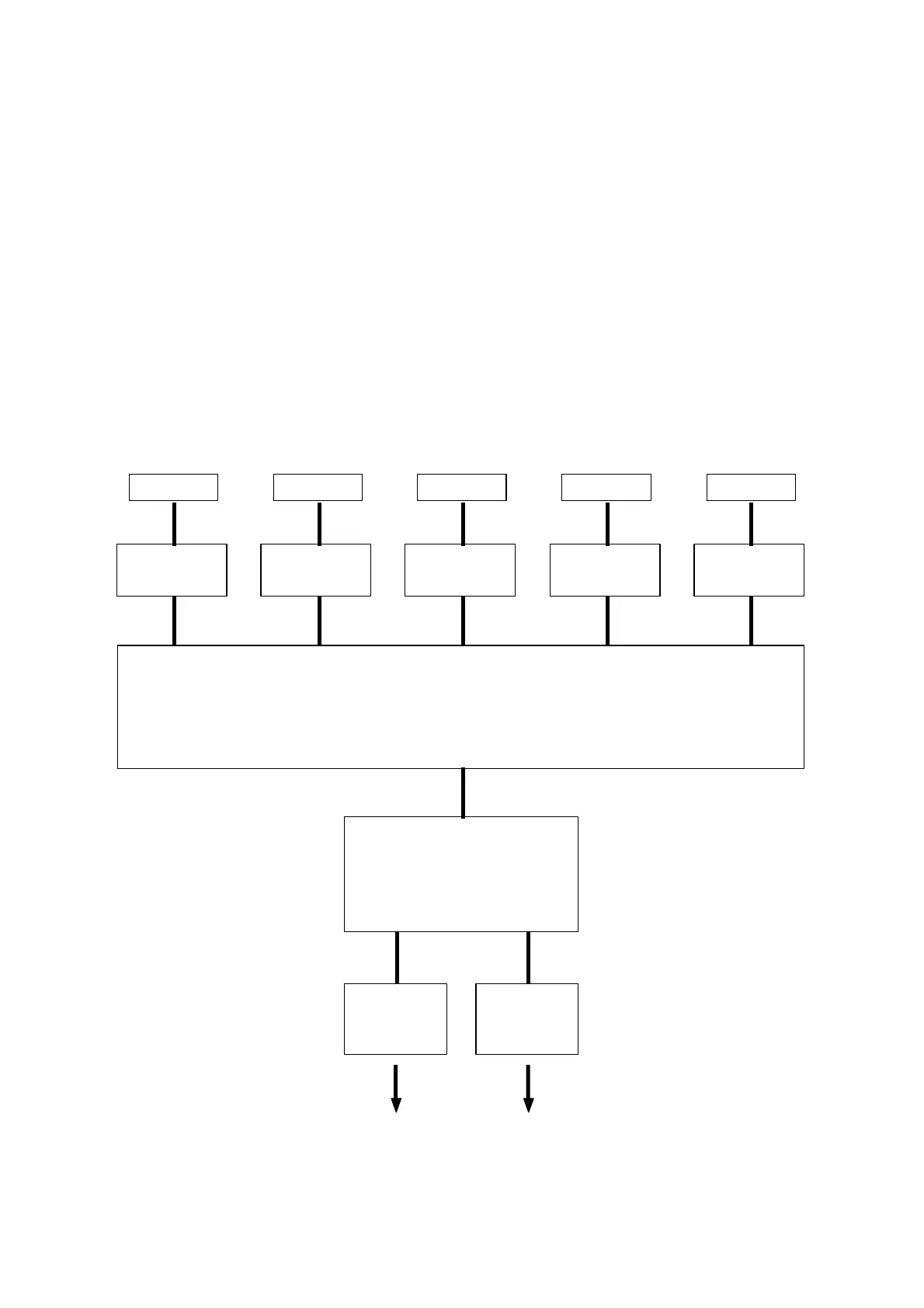
There are CIS Units, CIS Controller PCB (SVC CIS BD) and Main Board (SVC Main BD K) in the
scanner unit, which take image reading and processes the data.
1. The CIS Units read the image pattern of original, and then send the analog data to the CIS
Controller PCB.
2. The CIS Controller Boards converts the analog data into digital data, and then send to the Data
Controller PCB.
3. The Main Board takes the correct image process according to the UI setting.
Then it outputs the image data to the IPS through the USB 2.0.
4. The IPS output the image data to the printer part of KIP 700m through the Interface 8 in case of
“copy”, or it outputs to the Network PC through the LAN cable in case of “scan to file”.
CIS
CIS CIS CIS CIS
CIS Controller PCB
(A/D Conversion)
Analog data
Digital data
CIS Controller PCB
(A/D Conversion)
CIS Controller PCB
(A/D Conversion)
CIS Controller PCB
(A/D Conversion)
CIS Controller PCB
(A/D Conversion)
Main Board
(Several image process)
USB 2.0
IPS (Controller)
Interface 8 LAN
Printer part
Network PC /
color printer
Printing out
of the Copy
Save as file
Printer with color printer