K117sm8eE
8-224
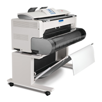
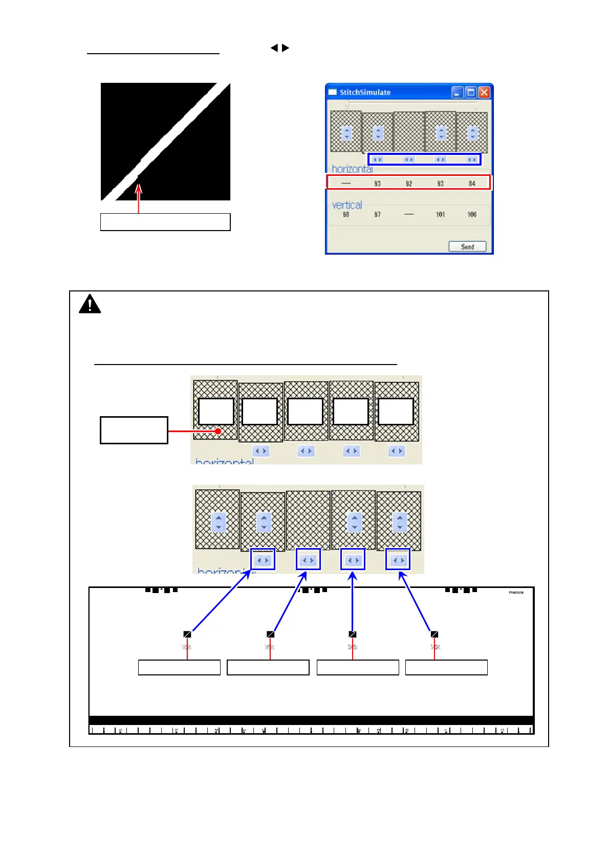
20. Second, correct horizontal misalignment as follows.
20-1. In “StitchSimulate” window
, click the buttons (see below in blue frame) to increase /
decrease the setting value for “horizontal” (see below in red frame). This moves the image
block horizontally.
Do the same way for all the 4 targets at the CIS borders if needed.
Setting values will turn red by setting changes. Setting value 1 step = 1 pixel to right
20-2. Image shifting (setting value in red) is not finalized yet. Click [Send].
Once the change is sent to the scanner’s Main Board, setting values turn black.
horizontal misalignment
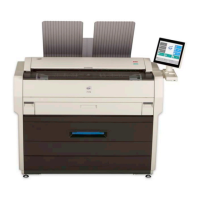
NOTE
(1) For horizontal correction, CIS 1 is the reference. You are asked to set the distance of shift
for CIS 2/3/4/5 against CIS 1.
First finalize the shift for CIS 2, and next CIS 3, CIS 4, CIS 5.
(2) The increase/decrease buttons correspond to the CIS border as follows.
Reference:
CIS 1
CIS 1
1st:
CIS 2
2nd:
CIS 3
3rd:
CIS 4
4th:
CIS 5
CIS 1 CIS 2 CIS 3 CIS 4 CIS 5
CIS1 to CIS2 CIS2 to CIS3 CIS3 to CIS4 CIS4 to CIS5