K117sm3e1
3-4
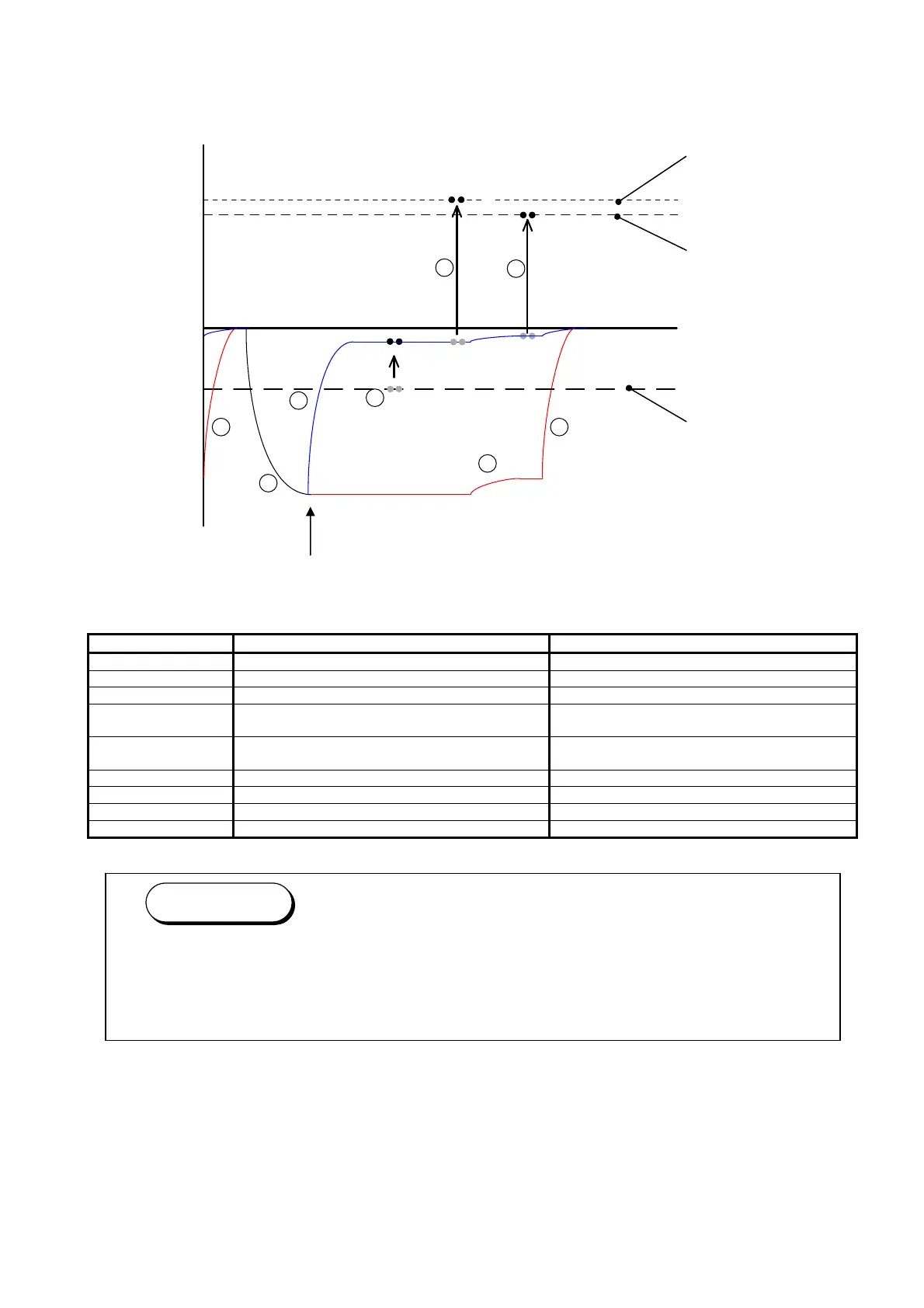
Processes from 1 to 8 are related with the control of the electric potentials.
The following graphic shows the electric potential at each process and the movement of toner.
Surface Potential of Drum
SP1 : For black image / SP2 : For white image
Name of part Voltage (Current) during Print Cycle Voltage during Toner Collection Process
Image Corona Wire -1.3mA +/-0.05mA -
Grid Plate -630V +/-30V -
Developer Roller -230V +/-5V +350V +/-5V
Regulation Roller
(Center)
-80V +/-5V against the Developer Roller Bias -80V +/-5V against the Developer Roller Bias
Regulation Roller
(Both sides)
0V (Connected to the ground) 0V (Connected to the ground)
Toner Supply Roller The same voltage with Developer Roller Bias The same voltage with Developer Roller Bias
Transfer Corona +1.0mA +/-0.05mA -
Separation Corona AC (5.0KV) + DC (-250V +/-5V) -
Cleaning Roller +450V +/-5V -550V +/-5V
0V
-100V
-200V
-300V
-400V
-500V
-600V
-700V
+400V
+300V
+200V
+100V
+500V
2
3
4
5
6
7
1
+600V
SP1
SP2
+700V
1
When the printer is going to stop after printing, or when the used Roll Deck is changed with
other one, the KIP 700m will take the “Toner Collection Process” to remove the remained
toner and place back into the Developer Unit.
Refer to [3.1.4 Toner Collection Process].
Reference
Voltage of
Cleaning Roller
Voltage of
Transfer Corona
Voltage of
Developer Roller