214323 313 Revision A
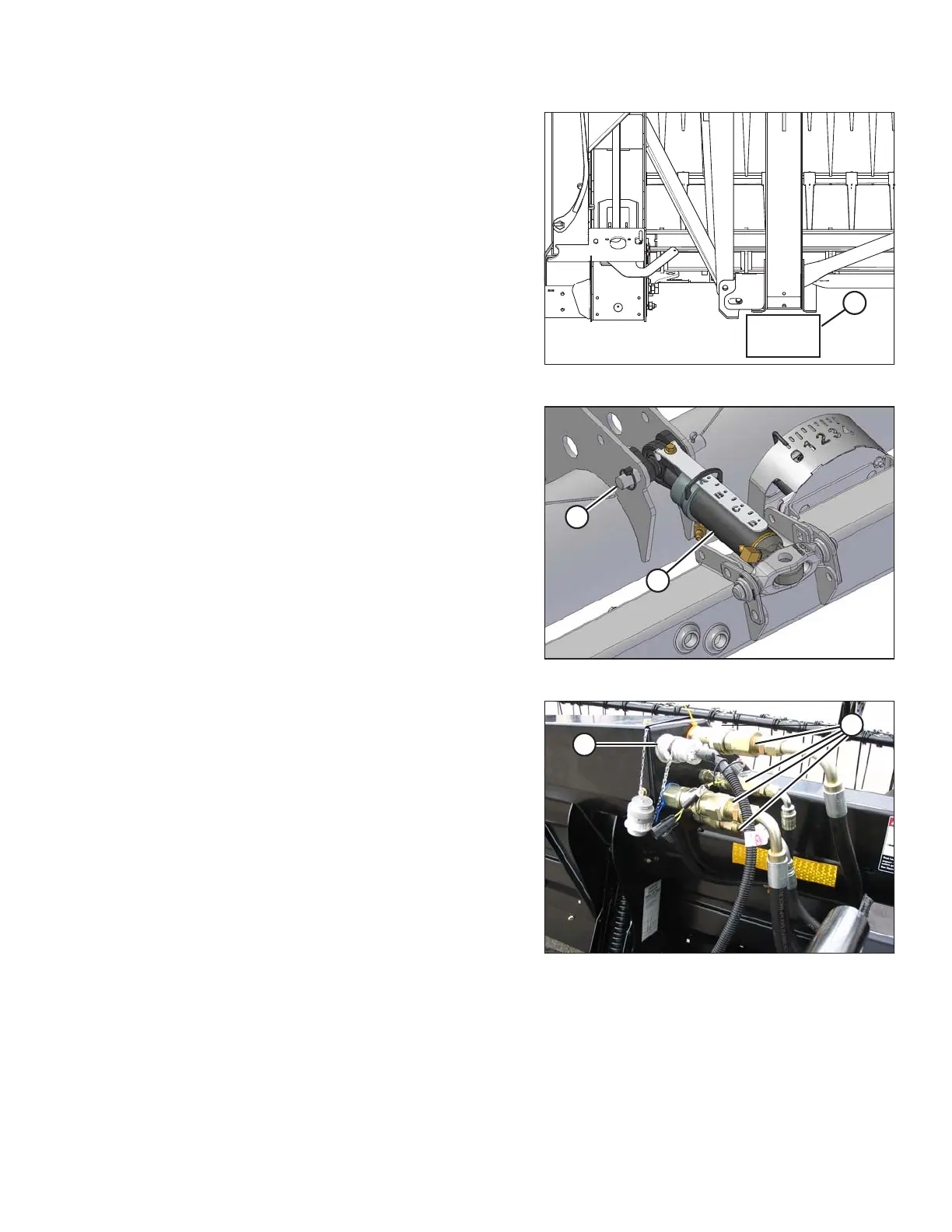
Figure 4.101: Header Leg on Block
18. Place a 150 mm (6 in.) block (A) under the header leg.
This will assist with disconnecting the center-link.
19. Disengage combine lift cylinder locks, start engine, and
lower header until the header leg rests on the block or
stabilizer wheels are the ground.
Figure 4.102: Hydraulic Center-Link
20. Disconnect the hydraulic center-link as follows:
a. Remove the lynch pin and clevis pin (A), and lift the
center-link (B) clear of the bracket.
b. Replace the clevis pin (A) and secure with
lynch pin.
NOTE:
It may be necessary to raise or lower the feeder
house to adjust the length of the center-link and
relieve excess load on the center-link.
Figure 4.103: Header Connections
21. Disconnect knife and draper drive hydraulic hoses (A).
Immediately cap hoses to prevent oil loss.
22. Store and secure the hoses on the adapter frame.
23. Disconnect electrical connector (B) by turning the collar
counterclockwise and pulling the connector to
disengage.
24. Store and secure the hoses and electrical connector on
the adapter.
NOTE:
• If on the ground: Push reel fully forward to reduce oil loss.
• If on transport: Pull reel fully back.
• If colored ties on hydraulic hoses are missing, replace them before disconnecting hoses.
HEADER ATTACHMENT/DETACHMENT