214323 389 Revision A
Checking Stub Guard Hold-Downs
This procedure is applicable to single- and double-knife headers with stub guards.
WARNING
To avoid bodily injury or death from unexpected startup of machine, always stop engine and remove key
before adjusting machine.
Measure clearance between hold-downs and knife sections as follows:
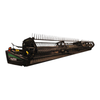
Figure 5.123: Standard Stub Forged Hold-Down
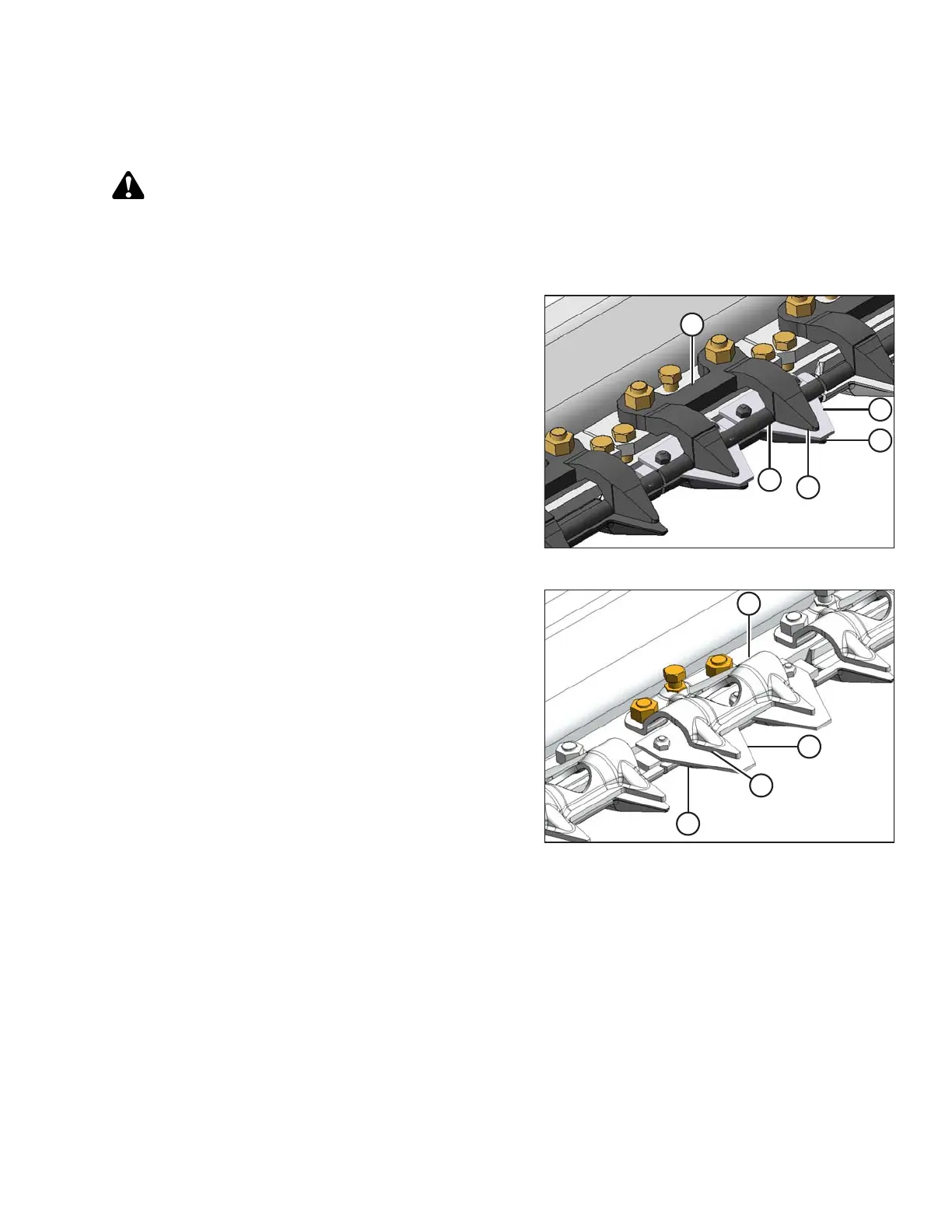
Figure 5.124: Standard Stub Sheet Metal
Hold-Down
1. Shut down combine, and remove key from ignition.
2. Manually stroke knife to locate section under hold-
down (A).
3. Standard guard: At standard guard locations, push
knife section (B) down against guard (C) and measure
clearance between hold-down (A) and knife section (B)
with a feeler gauge. The clearance should be as
follows:
• At hold-down tip (D): 0.1–0.4 mm
(0.004–0.016 in.)
• At rear of hold-down (E): 0.1–1.0 mm
(0.004–0.040 in.)
• At sheet metal hold-down (F): 0.1–0.6 mm
(0.004–0.024 in.)
4. If necessary, refer to Adjusting Stub Guard Hold-
Downs, page 390.
MAINTENANCE AND SERVICING