214323 390 Revision A
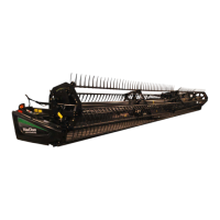
Figure 5.125: Double-Knife Center Stub Guard
Hold-Down
5. Double-knife center stub guard: Manually stroke
knife to locate sections under hold-down (B).
6. Measure clearance between knife sections (A) and (C)
with a feeler gauge. The clearance should be as
follows:
• At hold-down tip (E): 0.1–0.4 mm (0.004–0.016 in.)
• At rear of hold-down (F): 0.1–1.0 mm
(0.004–0.040 in.)
7. If necessary, refer to Adjusting Stub Guard Hold-
Downs, page 390.
Adjusting Stub Guard Hold-Downs
WARNING
To avoid bodily injury or death from unexpected startup of machine, always stop engine and remove key
before adjusting machine.
1. Shut down combine, and remove key from ignition.
Forged hold-down:
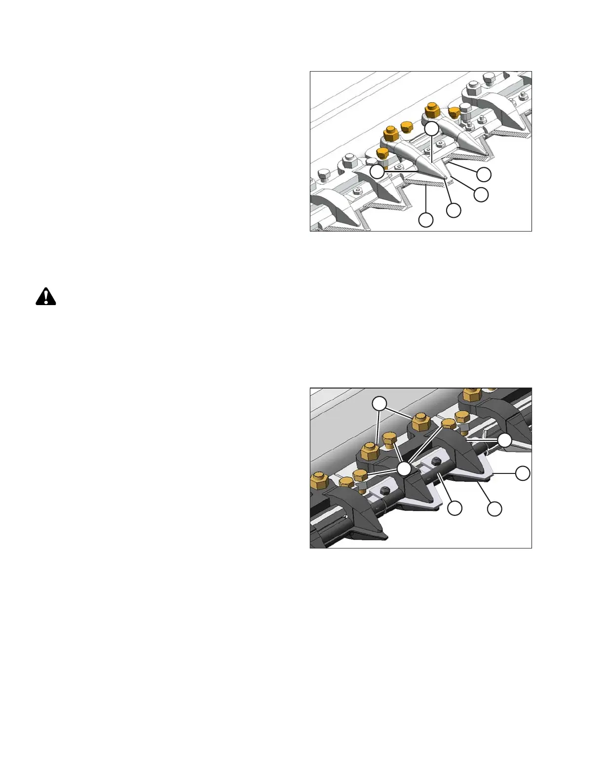
Figure 5.126: Normal Stub Guard Forged
Hold-Down
2. Manually stroke knife to center section(s) (A) under
hold-down (B) as shown.
3. Loosen nuts (C) and back off bolts (D) clear of
cutterbar.
4. Lightly clamp hold-down (B) to guard (E) with a C-clamp
or equivalent. Position clamp on trash-bar at (F).
5. Turn bolts (D) until they contact cutterbar, then tighten
ONE turn.
6. Remove clamp.
7. Tighten nuts (B) and torque to 45 Nm (35 lbf·ft).
8. Check that specified clearances are achieved. Refer to
Checking Stub Guard Hold-Downs, page 389.
MAINTENANCE AND SERVICING