215916 170 Revision A
Figure 4.121: Hydraulic Hose Management System
5. Connect hydraulic hose management system (A) to the
windrower by securing ball joint (B) to latch support (C) on
the windrower leg.
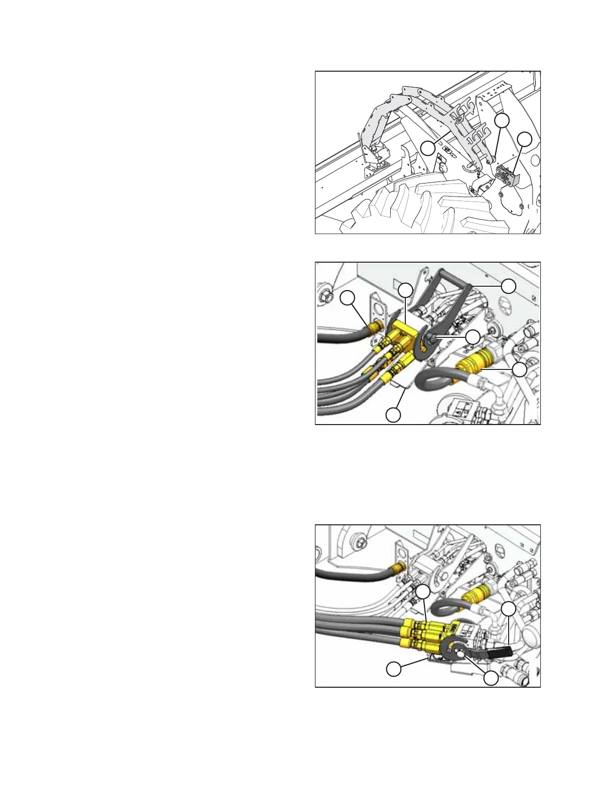
Figure 4.122: Draper/Reel Multicoupler
6. Retrieve draper drive and reel control multicoupler (A) from
the hydraulic hose management system.
7. Push knob (B) on the hydraulic receptacle and pull
handle (C) fully away from the windrower.
8. Open cover (D) and position the coupler onto the
receptacle. Align the pins in the coupler with the slots in
handle (C) and push the handle toward the windrower so
that the coupler locks onto the receptacle and knob (B)
pops out.
9. Remove hose quick-disconnect (F) from the storage
location and connect it to the receptacle on the frame.
NOTE:
Hose quick-disconnect (F) is only present on M1240
machines configured for draper/auger headers.
10. Remove the cover from electrical connector (E), push the
electrical connector onto the receptacle, and secure it by
turning the collar on the electrical connector clockwise.
Figure 4.123: Knife/Reel Drive Multicoupler
11. Retrieve knife and reel drive multicoupler (A) from the
hydraulic hose management system.
12. Push knob (B) on the hydraulic receptacle and pull
handle (C) fully away from the windrower.
13. Open cover (D) and position the coupler onto the
receptacle. Align the pins in the coupler with the slots in
handle (C), and push the handle toward the windrower so
that the coupler locks onto the receptacle and knob (B)
snaps out.
OPERATION