215916 473 Revision A
Installing Drive Wheels
Be sure to check the wheel nut torque again once the windrower has begun operation.
CAUTION
Use a lifting device capable of supporting a minimum of 907 kg (2000 lb.) to lift the wheel assembly.
IMPORTANT:
The windrower must be supported off the ground with stands while the drive wheels are being installed. For instructions,
refer to Raising Drive Wheel, page 471.
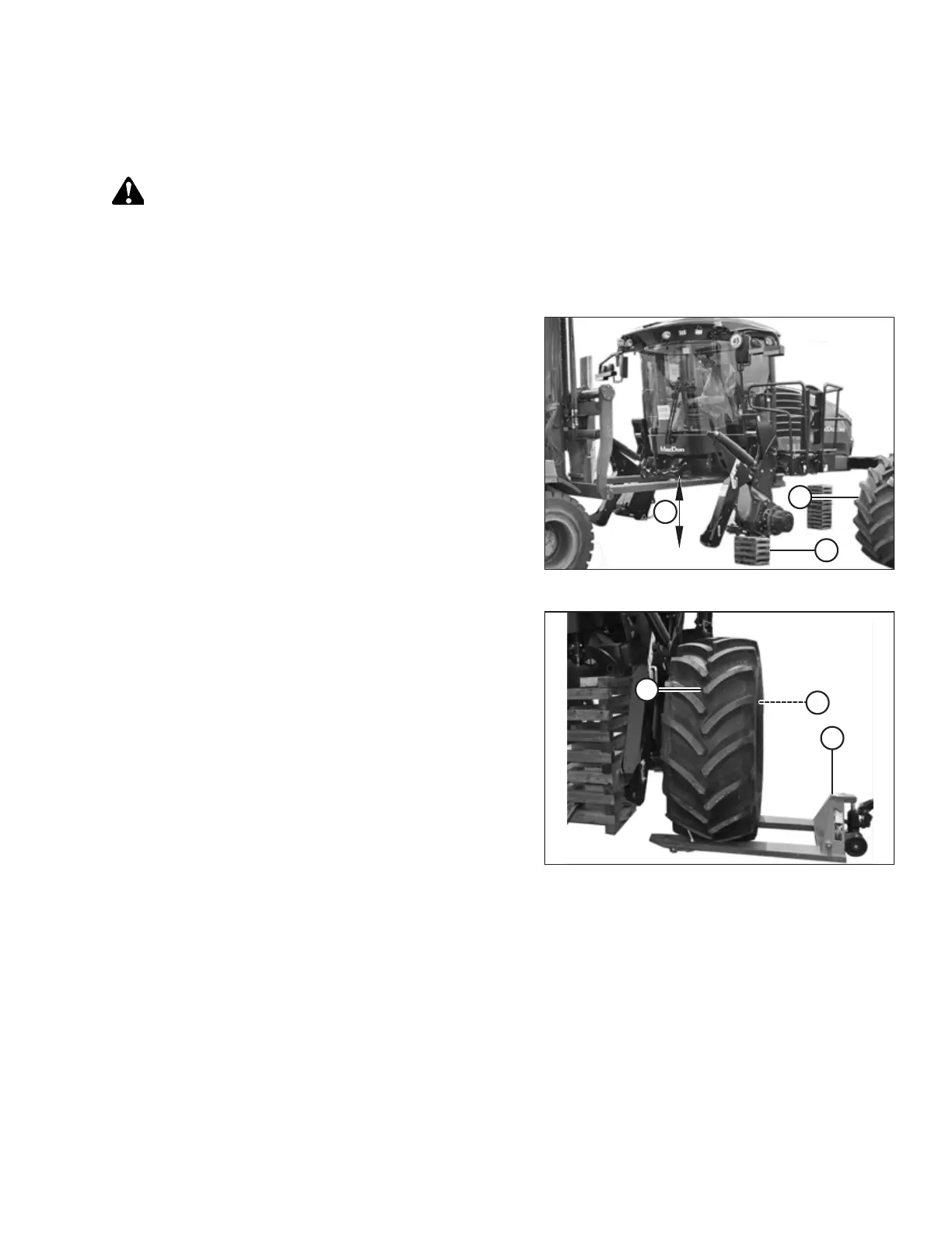
Figure 5.232: Windrower Supports in Place
1. Using a forklift, lift the cab end of the windrower
approximately 130 cm (51 in.) (B) off of the ground, or
enough so that left cab-forward drive wheel assembly (A)
can be positioned as shown. Place stand (C) under the
windrower frame.
2. Clean the mounting surface on the wheel drive and the rim.
Figure 5.233: Drive Wheel Ready for Installation
3. Position lifting device (A) under the wheel and raise the
wheel slightly.
4. Position the wheel against the wheel drive hub so that air
valve (B) is on the outside while tread (C) points
cab-forward.
NOTE:
For wheels equipped with turf tires (those with a diamond
tread pattern), be sure that the arrow on the sidewall
points cab-forward.
Figure 5.234: Tightening Sequence – 10-Bolt Wheel
5. Align the wheel rim with the studs on the hub. Push the
wheel onto the hub.
6. Install and hand-tighten wheel nuts (A).
IMPORTANT:
To avoid damage to the wheel rims and studs, do NOT use
an impact wrench to tighten the nuts. The stud threads
must be clean and dry. Do NOT apply lubricant or anti-seize
compound to the stud threads. Do NOT overtighten the
wheel nuts.
MAINTENANCE AND SERVICING