215916 474 Revision A
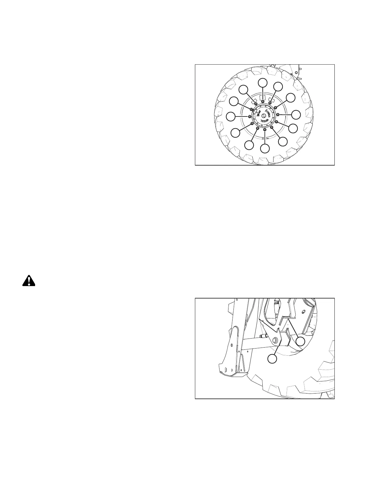
7. Torque the drive wheel nuts. For instructions, refer to 5.6.1
Tightening Drive Wheel Nuts, page 360.
Figure 5.235: Tightening Sequence – 12-Bolt Wheel
8. Repeat the tightening sequence two additional times, ensuring that the specified torque is achieved each time.
9. Repeat Step 2, page 473 to Step 8, page 474 in order to install the right drive wheel.
10. Raise the windrower, remove the stand, and lower the windrower to the ground.
11. Lower the windrower. Remove the jack. For instructions, refer to Lowering Drive Wheel, page 474.
12. Repeat the torque procedure every hour of operation until two consecutive checks confirm that there is no movement
of the nuts.
Lowering Drive Wheel
CAUTION
Jack stand must be capable of supporting a minimum of 2268 kg (5000 lb.).
Figure 5.236: Drive Wheel Leg Jacking Point
1. Place a jack under leg jack point (A), and raise the drive
wheel slightly off the jack stand.
2. Remove the jack stand from under cylinder lift mount (B).
Lower the drive wheel to the ground.
3. Remove the jack.
MAINTENANCE AND SERVICING