Figure 111: Drive compartment raised....................................................................................145
Figure 112: Remove air duct...................................................................................................146
Figure 113: Air duct.................................................................................................................146
Figure 114: Remove DIMMs ...................................................................................................147
Figure 115: Insert Controller
DIMM.........................................................................................148
Figure 116: DIMM alignment over DIMM slots........................................................................148
Figure 117: Reconnect cables to the backplane.....................................................................149
Figure 118: Insert air filter........................................................................................................150
Figure 119: Close Controller top cover....................................................................................151
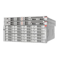
Figure 120: DE2-24P Drive Enclosure (front view)..................................................................153
Figure 121: DE2-24C Drive Enclosure (front view).................................................................154
Figure 122: DE2-24P Drive Enclosure (back view).................................................................155
Figure 123: DE2-24C Drive Enclosure (back view).................................................................155
Figure 124: DE2-24P Drive Enclosure drives..........................................................................156
Figure 125: DE2-24C Drive Enclosure drives..........................................................................156
Figure 126: A DE2-24P Drive Enclosure drive and drive carrier latch.....................................158
Figure 127: A DE2-24C Drive Enclosure drive and drive carrier latch....................................159
Figure 128: A drive removed from a DE2-24C Drive Enclosure..............................................159
Figure 129: A drive removed from a DE2-24P Drive Enclosure..............................................160
Figure 130: Extended drive carrier handles.............................................................................160
Figure 131: DE2-24C Drive Enclosure and inserted drive.......................................................161
Figure 132: DE2-24P Drive Enclosure and inserted drive.......................................................161
Figure 133: I/O modules on DE2-24P and DE2-24C Drive Enclosure types...........................163
Figure 134: I/O module SAS connector ports..........................................................................165
Figure 135: Remove the I/O module.......................................................................................165
Figure 136: Insert the I/O module............................................................................................166
Figure 137: I/O module SAS connector ports..........................................................................166
Figure 138: Power cooling modules (DE2-24P and DE2-24C Drive Enclosures)...................168
List of Figures
15
 Loading...
