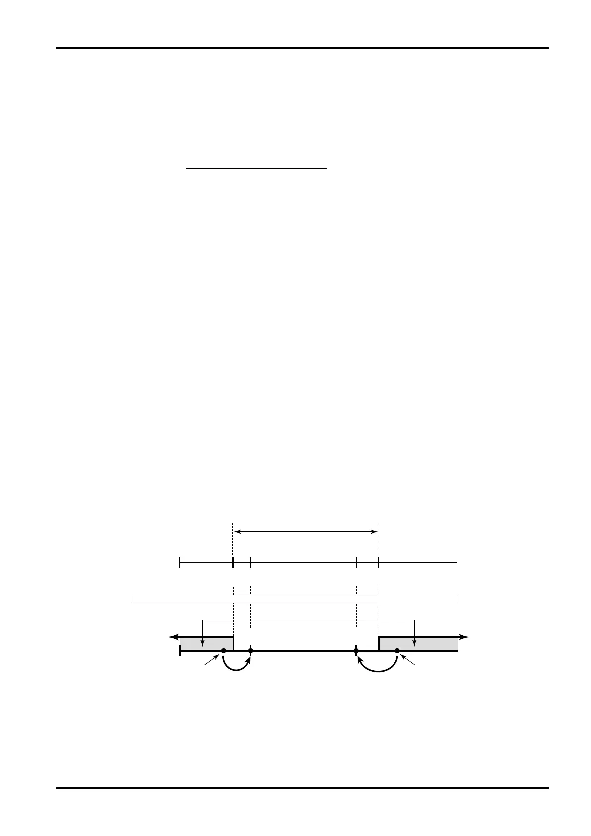
Example Measurement units (UNIT):g/l
Under alarm point(UNDER ALARM POINT):800g/l
Over alarm point(OVER ALARM POINT):850g/l
Under fallback level(UNDER FALLBACK):1150g/l
Over fallback level(OVER FALLBACK):1200g/l
850g/l
800g/l 1200g/l
1150g/l
Overfallbacklevel
Underfallbacklevel
Underalarmpoint Overalarmpoint
Measue.range
Max. full scale
Full
scale
Min. baseline
Base – full scale setting range
Base
line
Under
alarm pt.
Over fallback
level
Under
fallback level
Over
alarm pt.
Alarm output
Dens. input
800g/l 850g/l 1150g/l 1200g/l
Flowrate signal meas.Flowrate signal meas.
E-880TM-3-E
111
6.4.21 Density Calculation Setup (DENSITY PARAMETER), EL4311
Along with density calculation associated values, alarm points and fallback levels with respect to the
corrected density are set up here.
※ These settings are used only in Model EL4311. They are not shown in other models.
<Calculation Formula>
D
X
:Uncorrected density T
X
:Density period
D
W
:Density with water D
a
:Density with air
T
W
:Density period with water T
a
:Density period with air
t
W
:Water temperature during calibration t
X
:Line temperature
t
a
:Air temperature during calibration
α :Temperature compensation for tube spring constant
D
XC
:Corrected density
β:Reference temperature conversion factor of density t
0
:Ref. temp. for temp.
compensation
D
X
=(D
W
-D
α
)
[ ]
+D
α
T
X
2
(1 -
αt
X
)- T
α
2
(1 -
αt
α
)
T
W
2
(1 -
αt
W
)- T
α
2
(1 -
αt
α
)
D
XC
= D
X
+β(t
X
-t
0
)
Corrected density displayed in the RUN mode is shown in the measuring range where its high limit is at
the over alarm point while its low limit is at the under alarm point, corresponding to the input. If the input
exceeds or falls short of this range, the over or under alarm point is shown.