Max.fullscale
Fullscale
Min.baseline
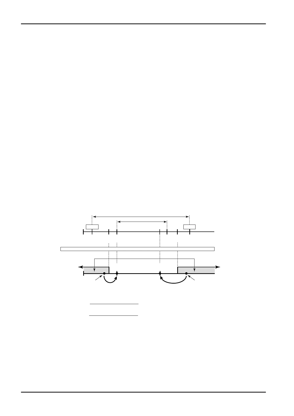
ExampleMeasurementunits(UNIT):℃
Baseline(BASESCALE):0℃
Fullscale(FULLSCALE):160℃
Underalarmpoint(UNDERALARMPOINT):−5℃
Overalarmpoint(OVERALARMPOINT):165℃
Underfallbacklevel(UNDERFALLBACK):5℃
Overfallbacklevel(OVERFALLBACK):155℃
Base‒fullscalesettingrange
Base
0℃ 160℃
350℃
−50℃
−5℃
3℃
5℃ 170℃
175℃
180℃
Underfallback Overfallback
Underalarmpt. Overalarmpt.
Meas.range
Alarmpoint‒fallback
settingrange
Max. full scale
Full
scale
Min. baseline
Base – full scale setting range
Meas. range
Base
line
350℃
Under
alarm pt.
Over fallback
level
Under
fallback level
Over
alarm pt.
Alarm output
Temp. input
−5℃ 0℃ 155℃ 160℃ 165℃
Flowrate signal meas.Flowrate signal meas.
−50℃
E-880TM-3-E
8
6.4 Submenu Setup Items
6.4.1 Temperature Input Setup (TEMP. INPUT)
As the factors associated with temperature, the measurement units, constants (with the input type set to
NONE in the SYS mode), baseline, full scale value, under alarm point, over alarm point, under fallback
level, over fallback level, and smoothing factor are established here.
※ In setting parameters, set the input type before the user sets these parameters, remembering
that definitions vary with the type of input (in the SYS mode).
(1) Pt 100Ω input
When “Pt100Ω” is your option in the input type (SYS mode), parameter definitions are as follows:
With Pt100Ωinput, the baseline-to-full-scale range is fixed. Set the baseline and full scale setpoint within
this range. (Failure to set them within this range will nullify assurance for proper operation.) The baseline
and full scale setpoint are referenced when the pulse output scaling is determined. Their settings should
be chosen, carefully taking into consideration the nature of calculation as well as the range of standard
span.
Temperatures in the RUN mode are indicated relative to the input within the range where the over alarm
point and the under alarm point determine its high and low limit, respectively. If an input goes out of this
range, the output will automatically be clamped at the over fallback or under fallback value.
Acceptable range of alarm points and fallback levels are determined by the following expressions:
(2) 4 to 20mA or 1 to 5V input
When the “4 to 20mA” or “I to 5V” input type is selected (SYS mode), respective parameters are defined
as follows:
With 4 to 20mA or 1 to 5V input, the baseline-to-full-scale setting range varies with the given model
(calculation). Set the baseline (or base scale) and full scale setpoint within the range acceptable by the
specific model used. (Failure to set them within this range will nullify assurance for proper operation.)
The baseline and full scale are referenced when the pulse output scaling is determined. Settings should
be determined carefully taking into consideration the process of calculation, value of standard span and
other contributing factors.
Alarm point and fallback setup range is determined as follows:
(i )Low limit Base scale-
Full scale - Baseline
×0.5
(ii )High limit Base scae+
Full scale - Baseline
×2
16
16