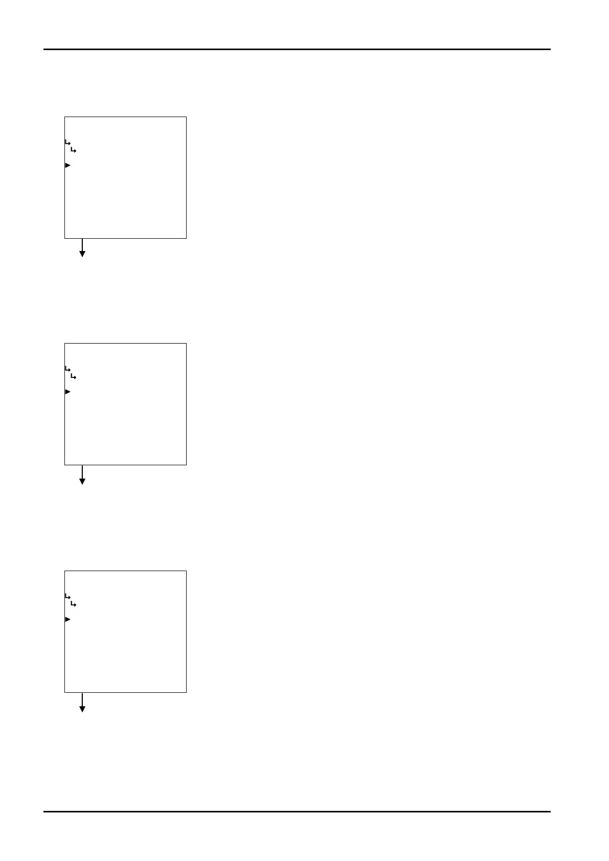
A−L
−−−−−<SYS MODE>−−−−−−
COMMUNICATION
S T O P BIT
1 bit
1:1 bit
3:2 bit
2:1.5 bit
−−−−−−<SELECT>−−−−−−−
|CAN−| |
EXIT| CEL| |ENTR
A−L
−−−−−<SYS MODE>−−−−−−
COMMUNICATION
ADDRESS
01
1:00
2:01
3:02
4:03
5:04
6:05
7:06
↓−−−−−<SELECT>−−−−−−−
|CAN−| |
EXIT| CEL| |ENTR
A−L
−−−−−<SYS MODE>−−−−−−
COMMUNICATION
DATA BIT
8 bit
1:7 bit
2:8 bit
−−−−−−<SELECT>−−−−−−−
|CAN−| |
EXIT| CEL| |ENTR
E-880TM-3-E
18
Communication setup submenu screen p. 166
③ Communication data bit length setup (DATA BIT)
Communication data bit length is set up here.
④ Communication stop bit length setup (STOP BIT)
Communication stop bit length is set up here.
⑤ Communication home address setup (ADDRESS)
Home address of communication is set up here. “00” to “0F” can be chosen for home address.
←Communication data bit length option select
For details of option setup, see “(2) Option select setup screen (SELECT)” on
page 46.
Communication setup submenu screen p. 166
Communication setup submenu screen p. 166
←Data stop bit length option select
For details of option setup, see “(2) Option select setup screen (SELECT)” on
page 46.
←Data bit length option select (setup)
For details of option setup, see “(2) Option select setup screen (SELECT)” on
page 46.